

Drawings and documents
National Archives restored drawings: drawing
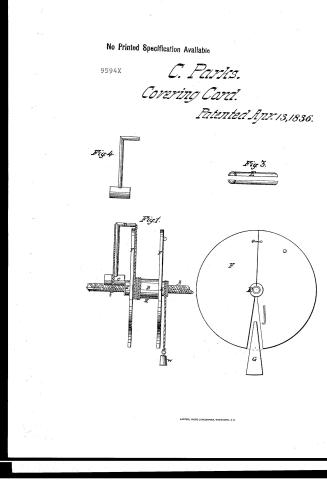
Charles Parks' Patent Drawing for a Machine for Serving Ropes

National Archives, Restored Patent Drawings (Record Group 241) · Full-size scan at the National Archives · Catalog record
Show the text on the drawing Hide (45 words)
Words on the drawing as machine-read by the National Archives; not checked. Useful mainly for searching.
28. CORDAGE / [17] Covering Cord. / $12 / No 283 / to / CHARKES / 9594.X / Ropes. / DIVISTONT / Patented 73 April 1836 / 9594 / Fig. 4 / Fieg 3 / Fig.1 / Scale / lipied from the Original to the Patent, by Henry Stone / to The / Dec.20.1636 / Assession
USPTO scan
The patent as scanned by the USPTO
-
 Page 1
-
 Page 2
-
 Page 3
-
 Page 4
-
 Page 5


U.S. Patent and Trademark Office · Google Patents
Show the transcription Hide (993 words)
Machine transcription (LightOnOCR) of the pages as scanned by the USPTO, most of them the handwritten copies made when the records were restored after the 1836 fire. Not checked; it can misread handwriting, so compare it with the scan.
Page 1.
No Printed Specification Available
9594X
C. Parks.
Covering Card.
Patented Apr. 13, 1836.
Fig. 4
Fig. 3
Fig. 1
Page 2.
Charles Parks, who has declared his intention to become a Citizen of the United States.
No. 2,835. "Improvement in a machine for drawing Ropes"
Date of Patent: 13th April 1836
Certificate of Attorney: 13th April 1836
The Specification referred to in these Letters Patent and making part of the same, containing a description in the words of the said Charles Parks himself, of his improvement in the "machine for drawing Ropes"
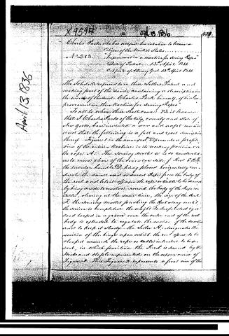
To all to whom these shall come: We, the undersigned, that I, Charles Parks of the City, county and state of New York, have invented a new and useful machine and that the following is a full and exact description thereof. Figure 1 in the annexed represents a profile view of the entire machine in its working position on the rope. A. The drawing wheel C is so constructed as to move clear of the lower or lower side of the reel &c. the tubular handle D, being placed horizontally and close to the wheel and drawn rope from the body of the reel and lets it off on the rope or cable to be drawn by being made to revolve around the body of the rope or cable, clearing at the same time, the size of the reel. F. the drawing wheel pushing the reel along until the service is completed. The weight E, the foot pedal G and lever in a groove over the outer end of the reel body is extended to regulate the motion of the machine and to keep it steady. The letter H designates the position of the hinge upon which the reel opens to be clamped around the rope or cable intended to be drawn, in which position the reel is drawn by the hooks and staple represented on the upper curve of Figure 2. This Figure 2 represents a front view of the
Page 3.
424 9594X
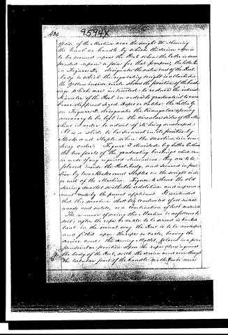
Off side of the Machine near the weight W, showing the hook or handle by which the device is to be wound upon the reel when the latter is suspended upon a pin for that purpose, the letter E in Figure 2, designates the outer end of the reel body to which the regulating weight is attached. The yellow inside circle shows the position of the bushings which are intended to reduce the internal diameter of the reel in order to graduate it to encompass different sized ropes or cables; the letter F in Figure 2, designates the triangular opening necessary to be left in the circular sides of the Machine in order to admit of its being unclasped. H is a slide to be secured in its position by hooks and staples when the Machine is in working order. Figure 3 delineates by letter E, the two parts of the graduating bushings which can be made of any required dimensions; they are to be placed inside the reel body, and secured in position by two hooks and staples on the weight side or end of the Machine. Figure 4 shows the old serving mallet with the addition and improvement made by the present applicant. It is intended that this machine shall be constructed of all suitable woods and metals, or a combination of both materials.
The manner of using this Machine is as follows: to start after the rope to cable to be served is handled out in the usual way the reel is to be unclasped and fitted upon the rope or cable, leaving the device cool; the serving mallet, placed in a perpendicular position upon the rope close against the body of the reel, with the device and rope through the tubular part of the handle, the hand is moved
Page 4.
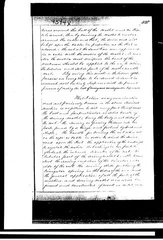
turns around the butt of the Mallet and the Rope to be turned, thus by causing the Mallet to revolve around the Cables and Rook, the Strain and will be left upon the Cables in proportion as the Rook is relieved. The Rook at the same time moving forward in a ratio with the motion of the Mallet. It requires the motion most uniform the hand of the workman should be applied to the angle where the tubular and solid parts of the Mallet handle meet. By using this machine the labour of the person on every rope to be turned is saved inasmuch as it entirely dispenses with the present process of casting the Cables of Sizing and winding on the Ropes.
That I claim as my own invention and not previously known in the above described machine is as follows to wit: every part thereof except the butt and perpendicular or solid handle of the Sizing Mallet; being the body and sides of the Rook; the Sizing or forming the same into two parts joined by a hinge and fastened by hook and staple; the handle for turning the Rook which set on the rope or Cable in order to wind the Strain and upon the Rook the application of the endwings to regulate the motion the bushing in two parts to graduate the internal diameter of the Rook; the tubular part of the Sizing Mallet handle being about the Sizing and clear of the Circular outer side of the Rook the Sizing slide for closing the triangular opening in the sides of the Rook and the general application of all the parts of the machine and Sizing Mallet as a whole is formed and constructed of wood or metal, etc.
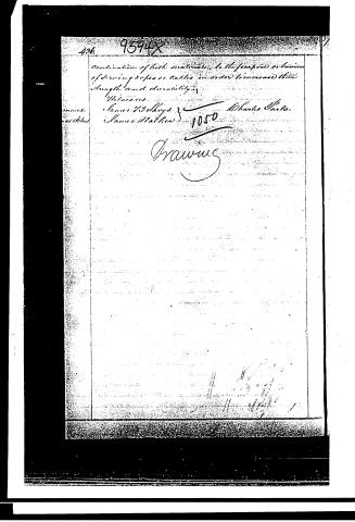
Page 5.
436 9594X
Combination of both materials, to the purpose of business of serving ropes or cables in order to increase their strength and durability.
Witnesses:
James T. Shroyd
James Walker
Charles Parker
1050
Drawing
Published accounts: journal notice
Notice in the monthly list of patents
Journal of the Franklin Institute, new ser., vol. 18 (1836), p. 71 · View the page
283. Serving ropes. Charles Parke, N. Y.
About this record
- Patentee
- DATAMP
- Date
- the Name and Date index of patents, DATAMP, USPTO records
- Invention
- DATAMP
- Listed in
- the Name and Date index of patents, DATAMP, USPTO records, Jim Shaw's X-patent list, the Journal of the Franklin Institute, Burke's List of Patents (1847)
- Burke's 1847 Patent Office list gives the same patent.