

Drawings and documents
National Archives restored drawings: drawing
S. Russell's Patent Drawing for an Excavator

National Archives, Restored Patent Drawings (Record Group 241) · Full-size scan at the National Archives · Catalog record
Show the text on the drawing Hide (77 words)
Words on the drawing as machine-read by the National Archives; not checked. Useful mainly for searching.
S o RUSSELL / CLACSIL loation / Excarator / citles / 9631.4 / DIVISION. / Ratinted / 9631X / Paterite / steveson are / scoop / in / startly catcheste / scann in He position for aircharging / when tillia and rea / bedischanged / P. / thank / nieveher all / are toberemented / R. crane / 64 / the / as / the / Patent office Mar 6.29th 1517 / Made under the eterection? of the commissions patents / in conformer ty with act it March 1837- / the / Pown
USPTO scan
The patent as scanned by the USPTO
-
 Page 1
-
 Page 2
-
 Page 3
-
 Page 4
-
 Page 5


U.S. Patent and Trademark Office · Google Patents
Show the transcription Hide (1,587 words)
Machine transcription (LightOnOCR) of the pages as scanned by the USPTO, most of them the handwritten copies made when the records were restored after the 1836 fire. Not checked; it can misread handwriting, so compare it with the scan.
Page 1.
9631X
S. RUSSELL.
EXCAVATOR.
Patented Apr. 28, 1836.

Page 2.
9631X
Apr 28-1836
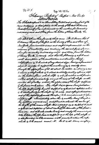
Silvanus Russell of Buffalo New York
Letters Patent
The Schedule referred to in these Letters Patent and making part of the same containing a description in the words of the said Silvanus Russell himself of his improvement in the machine for excavating and raising mud and stones from the bottom of Rivers, Docks, &c.
To all to whom these presents shall come. Be it known that I Silvanus Russell of Buffalo in the county of Erie and State of New York have invented a new and useful improvement in the manner of constructing and combining the several parts of a machine for excavating and raising mud and stones from the bottom of Rivers, Docks, or canals, and that the following is a full and exact description of the construction and operation thereof.
A platform is to be made of any desired size, having a framework above it in order to support the machinery as is usually done. Through the upper floor of it at about the centre, an opening is made to receive a shaft which is to stand vertically resting upon a step in the bottom floor, which step is also furnished with friction rollers set perpendicularly around the axis of the shaft, and the similar set of rollers receive the upper axis of the shaft supported by the framework alone. This shaft has a square base just above the step sufficiently broad to support a cylindrical capstan which is to revolve freely on the shaft as its axis, and a projection at each end of this capstan prevents the rope (to be wound round it) from slipping off. Immediately above this is another band (though in this instance around one) and placed in almost the centre of the length of the main shaft, and intended as a support to another cylindrical capstan of about one half the diameter of the first or lower one, and will also revolve loosely and occupy the remaining distance between the top base or support and the top of the shaft. It is also provided in the manner with guards to retain the rope which is to be wound round it, as it is at times necessary.
Page 3.
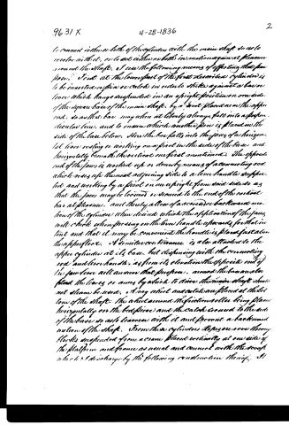
to connect either or both of the cylinders with the main shaft so as to revolve with it, or to set either or both in motion against pleasure around the shaft. I use the following means of effecting that purpose. First at the lower part of the first described cylinder is to be inserted a pin or catch in order to strike against a bar or lever which hangs suspended in an upright position on one side of the square base of the main shaft, by a pivot placed near the upper end, so as the bar may when at liberty always fall into a perpendicular line, and to ensure which another pin is placed in the side of the base below. Here the bar falls into the jaws of a horizontal lever resting or working on a pivot in the side of the base and horizontally beneath the vertical one first mentioned. The opposite end of the jaws is worked up or down by means of a connecting rod which rises up the next adjoining side to a lever handle supported and working by a pivot on an upright from said side so as that the jaws may be closed or opened to the end of the vertical bar at pleasure, and thereby allow of a backward motion of the cylinder when desired which the application of the jaws will check when pressing on the lever handle upwards for that intent and that it may be convenient the handle is placed fast above the upper floor. A similar contrivance is also attached to the upper cylinder at its base, but dispensing with the connecting rod and lever handle, as from its elevation the opposite end of the jaw lever will answer that purpose. Around the base are also placed the levers or arms by which to drive the main shaft should not steam be used. A ring wheel and catch are placed at the bottom of the shaft. The wheel around the friction roller being placed horizontally on the bed piece and the catch secured to the side of the base so as to groove with it and prevent a backward motion of the shaft. From these cylinders ropes or cords through blocks suspended from a crane placed vertically at one side of the platform and frame as usual and connected with the scoop which I discharge by the following construction thereof.
Page 4.
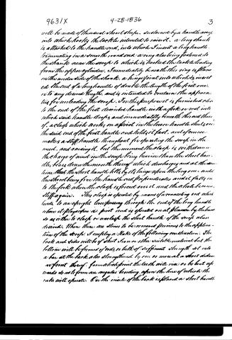
will be made of the usual scoop shape, sustained by a handle arcing into which hooks the tackle intended to raise it. A long shank is attached to the handle end, into which I insert a long handle terminating in a smooth round end a ring also being fastened to the shank near the scoop to which is hooked the tackle leading from the upper cylinder. Immediately beneath this ring is placed on the under side of the shank a hinge joint into which is inserted the end of a long handle of double the length of the first one, to any desired length, and is intended to contain the apparatus for unloading the scoop. For this purpose it is furnished close to the end of the first described handle with a fork or rest into which said handle drops and immediately beneath this end there of a clasp which works on a pivot in the loose handle shut over the said end of the first handle and holds it fast, and of course makes a stiff handle throughout for operating the scoop in the mud, and raising it. But the moment the clasp is withdrawn the charge of mud in the scoop being heavier than the short handle, bears down the mouth thereof which discharges and at the same time that the short handle falls by its hinge upon the long one, until the short being free the handle end preponderates and it falls in to the fork when the clasp is forced over it and the whole becomes stiff again. This clasp is operated by means of a connecting rod which leads to an upright lever passing through the end of the long handle where it plays upon a pivot and is operated on all planes by the hand so as either to clasp or unclasp the short handle of the scoop when desired. When there are stones to be removed previous to the application of the scoop, I employ a rake of the following construction. The back and sides will be of sheet iron or other suitable material but the bottom will be formed of rods or teeth of sufficient strength set into a bar at the back, also strengthened by one or more at a short distance in front thereof. From a high point the teeth will rise or be bent upwards so as to form an angular bending upon the line of which the rake will operate. On the inside of the back is placed a short handle.
Page 5.
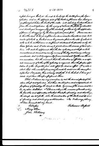
or pole having a hook at the end to hook into the tackle from the lower cylinder, and on the opposite side of the back is placed a bow, having an eye placed just below the back of the rake into which is hooked the tackle from the small cylinder, by the rising of which the rake is elevated and discharged consequently of the contents gathered by the application of power in dragging by the lower cylinder and pole. From one end to the other and behind is placed a semicircular handle or rod, to the centre of which is hooked on a long wooden pole or handle by which the rake is to be withdrawn a sufficient distance to be operated on by the lower cylinder and it also serves to guide it on the course of said operation. It will be apparent that the two cylinders and shaft will be connected and secured as one by means of the key contrivance already mentioned, and will consequently leave round all together as the arms are moved on, but the moment that the elevation is effected, or a separate movement of either of the cylinders is required, then the proper application to either horizontal jaw will effect the desired effect. It is also evident that other modifications may be made to avail on the same principle but I consider these already set forth to be the best I have yet used and have therefore preferred them.
What I claim as my invention is not the several parts of the above shaft and cylinders, but their combination and adaptation to the purposes of operating the scoop or rake, by means of the crank and tackles as above described. I likewise claim the manner of constructing the handles and apparatus attached thereto for operating and discharging the scoop as set forth, also the construction of the rake and its mode of operating and discharging as stated above. In testimony whereof I have hereunto set my hand.
Witnesses
Henry Stone
Jno. Williams
Salvannes Russell
Published accounts: journal notice
Notice in the monthly list of patents
Journal of the Franklin Institute, new ser., vol. 18 (1836), p. 71 · View the page
320. Excavating from rivers, &c.-Silvanus Russel, Baffalo, N. Y.
About this record
- Patentee
- DATAMP
- Date
- the Name and Date index of patents, DATAMP, USPTO records
- Invention
- DATAMP
- Listed in
- the Name and Date index of patents, DATAMP, USPTO records, Jim Shaw's X-patent list, the Journal of the Franklin Institute, Burke's List of Patents (1847)
- The Franklin Institute's journal spells the name differently.
- Burke's 1847 Patent Office list gives the same patent.