

Drawings and documents
National Archives restored drawings: drawing
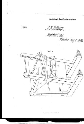
A.H. Robbin's Patent Drawing for a Vegetable Cutter

National Archives, Restored Patent Drawings (Record Group 241) · Full-size scan at the National Archives · Catalog record
Show the text on the drawing Hide (18 words)
Words on the drawing as machine-read by the National Archives; not checked. Useful mainly for searching.
as / off
USPTO scan
The patent as scanned by the USPTO
-
 Page 1
-
 Page 2
-
 Page 3
-
 Page 4
-
 Page 5


U.S. Patent and Trademark Office · Google Patents
Show the transcription Hide (1,253 words)
Machine transcription (LightOnOCR) of the pages as scanned by the USPTO, most of them the handwritten copies made when the records were restored after the 1836 fire. Not checked; it can misread handwriting, so compare it with the scan.
Page 1.
No Printed Specification Available
9639X
A. H. Robbins,
Vegetable Cutter.
Patented May 6, 1836.
Page 2.
May 6, 1836
Auction to Robbins of Denmark, N. York
Letters Patent.
The schedule referred to in these letters patent, and making a part of this issue, containing a description in the words of the said inventor H. Robbins himself of his improvement in the machine for cutting Potatoes, Turnips, Mangels, swage, carrots, &c. for cattle and horse feed.
Be it known that I, the said H. Robbins of Denmark, of the County of Lewis & State of New York, have invented a new and useful machine for cutting Potatoes, Turnips, mangels, swage, carrots, &c. for feeding to cattle, horses and other domestic animals. The drawing herewith enclosed, is a view in perspective of the model of said machine, on a scale of half an inch to the inch of said model, which is on a scale of three inches to the foot of said machine for use (or nearly).
The principle timbers are four feet and 3 bed pieces or sills, which may be 2 by 3 and a half inches square. The front posts may be 4 feet & 4 inches in length. The rear post 3 feet 4 inches and the bed pieces or sills 3 feet 4 inches in length. Each bed piece receives the foot of one front and one rear post, leaving a space of 10 1/2 inches between. The ends of the bed pieces are received extending forward. Three feet from where the foot of the rear post enters the bed piece is inserted a girt about 2 inches wide and twenty inches in length, upon the upper side the opposite the opposite end of which is received by the front post, which is very movable inclined forward as the rear post enters the bed piece without a base. These timbers, thus put together constitute the side frames of the machine. The width of said machine may be 20 inches between the posts. The sides are joined connected.
Page 3.
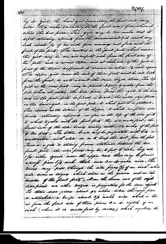
by 4 girts, the lower girt connecting the front post may enter 18 1/2 inches (measuring on the front side) from where it enters the bed piece. This girt may be two inches deep its depth extending upwards from the measurement of its width may lack about 1/4 of an inch from coming out full with the front of the post. The mortises in the front post which receive the girts may be one and one-half inch from the front side of the post and a corner tenon cut at each end of this girt in front of the tenon sufficient to receive a slide 1/2 inch square. The upper girt near the end of these posts must be set back from the front to act about the same sized slide. The top girt in the rear post may be placed 2 feet 9 inches from the post where it enters the bed piece. From this girt to the lower end in the front post is placed a board, the under edge placed on the lower girt in the front post to which girt it is fastened. This serves as the bottom of the hopper to which one foot is hinged extending upwards as far as the top of the side girt to which together with the front post they are made fast, the lower end of the side board coming within 1/2 inch of the front of the post. The bottom board may be proportioned with lots or constructed with slats so as to keep the dirt from the feed. There is a gate or sliding frame stationed between the two front posts. The side pieces may be 2 feet 6 inches long and 1/4 inch square near the upper end there may be formed a cross piece 1/3 inch thick and 3 or 4 inches wide. The tenons may pass through the side pieces 3/8 of an inch which will serve as tongues which slide in the grooves cut on the inside of the front posts, at the lower end of the side piece there are other tongues or projections for the same object. To these same pieces about 9 inches below the cross piece is attached a knife about 3 1/2 inches wide which is let in from the front side of these pieces 3 or 4 eighths of an inch (where it is made fast by screws) which regulates the
Page 4.
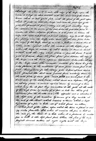
thick enough the line is to be cut. The edge of the knife upon the inside is to pay no close contact with the lower end of the bottom board which is not quite full with the front of the gate upon which it rests, so that the knife rest near the front edge of the gate. To prevent it from cutting into the gate something may be attached to the inside of the post below the gate door piece to receive the blow. A piece of board is to be placed so between the knife and upper edge piece as to prevent whatever may be in the hopper from falling over the knife when down. On the line piece below the edge of the knife about 1/2 an inch is fastened a board 12 or 15 inches wide against which the contents in the hopper press when the knife is raised by which means it comes in direct contact with the edge which stands in from the board 2 as the gate is pressed down the feed falls from between the edge of the knife and the board upon a conductor below when the edge of the knife rests. This conductor consists of a board 6 or 7 inches wide fastened to the underside of said piece made fast to the post. Enough room for the sliding gate to pass up and down. To prevent the dirt and gravel from working down by the side piece of said gate small slots are made fast to the lower end of the said board which serve as a defense. The gate or sliding frame is raised up and down by means of a lever which may be 4 feet long connected to the gate at the center of the edge piece by means of a pin or bolt two thirds of its distance from the handle end. The opposite end is attached to the left side of the machine by means of a long moister at the end of the lever which receives a tension which is kept by means of a pin or bolt, all of which forms an elbow. That part of the elbow upon which the tension is placed is about 9 1/2 inches from the hole where it receives the pin or bolt at the end of the lever to a hole where it is fastened by another pin or bolt to the left front post. Above the face of the knife project several cutters at right angles with the knife.
Page 5.
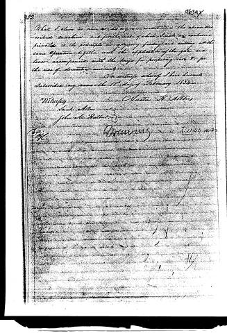
What I claim as new or as my own invention is the above described machine and for the use of which I have an exclusive privilege is the principle in grinding, feeding and cutting at the same operation together with the application of the gear and lever accompanied with the knife for preparing roots &c for the use of domestic animals.
In witness whereof I have hereunto subscribed my name the 15th day of February 1834.
Austin H. Atkins
Witness
Frank Allen
John A. Buller
Recorded
February 20, 1834
Published accounts: journal notice
Notice in the monthly list of patents
Journal of the Franklin Institute, new ser., vol. 18 (1836), p. 143 · View the page
336. Cutting vegetables. Austin H. Robbins, Denmark, N. Y.
About this record
- Patentee
- DATAMP
- Date
- the Name and Date index of patents, DATAMP, USPTO records
- Invention
- DATAMP
- Listed in
- the Name and Date index of patents, DATAMP, USPTO records, Jim Shaw's X-patent list, the Journal of the Franklin Institute, Burke's List of Patents (1847)
- Burke's 1847 Patent Office list gives the same patent.