

Drawings and documents
National Archives restored drawings: drawing
David Wilkinson's Patent Drawing for a Canal Lock Gate

National Archives, Restored Patent Drawings (Record Group 241) · Full-size scan at the National Archives · Catalog record
Show the text on the drawing Hide (50 words)
Words on the drawing as machine-read by the National Archives; not checked. Useful mainly for searching.
il HYDRAULIC ENGINEERING. / [82] Canals. / CLASSIFICATION / 9.660.1 / David / Milinsons / DIVISION. / 9660X / Canal Lock Gaie. / Patenied / Perspective view knewing the Valve open / Geomedrical view shewing the Valve shur. / iB / Franc'. / E, / OA / side / (CO / IH / JH / III
USPTO scan
The patent as scanned by the USPTO
-
 Page 1
-
 Page 2
-
 Page 3


U.S. Patent and Trademark Office · Google Patents
Show the transcription Hide (747 words)
Machine transcription (LightOnOCR) of the pages as scanned by the USPTO, most of them the handwritten copies made when the records were restored after the 1836 fire. Not checked; it can misread handwriting, so compare it with the scan.
Page 1.
9660X
D. Wilkinson.
Canal Lock Gate.
NO PRINTED SPECIFICATION AVAILABLE
Patented May 14, 1836.
Perspective view showing the Valve open.
Geometrical view showing the Valve shut.
Page 2.
May 14, 1836
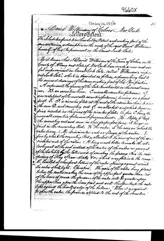
David Wilkinson of Cohoes New York
Selters Patent
The Schedule referred to in these Letters Patent and making part of the same containing a description in the words of the said David Wilkinson himself of his Improvement in the Canal Lock Gate.
Be it known that I David Wilkinson of the Town of Cohoes in the County of Albany and State of New York have made a new and useful improvement in Canal Lock Gates, called "Wilkinson's improved Lock Gate," which is described as follows, reference being had to the annexed drawings of the same making part of this Specification.
A represents the frame of the Gate constructed in the usual manner. B, an eccentric lever. C, a movable eccentric fulcrum. D, an end support of the movable eccentric fulcrum, turning on a fixed pivot. E, F, a circular plate at the end of the eccentric lever to which the arm D, and connecting rod G, are attached and which lever or pins are inserted in the rim of the circular plate, the pin C being the movable eccentric fulcrum before mentioned. H, staples to keep the connecting rod and arm in their proper positions. I, hinges or joint in the connecting Rod. K, the valve. L, the axis on which the valve turns. M, a semicircular end or flange of the valve. N, pins by which the connecting Rod is attached to the end of one of the semicircular ends of the valve. It being much better to make the attachment at the end instead of the centre of the valve on account of the liability by the latter mode of connecting the passage thro' the valve opening of clay straw sticks &c, which may fall into the canal. O, bevelled or chamfered bottom of the valve opening against which the valve shall light.
Operation. The axis of the valve being placed below the centre makes the area of the upper part greater than that of the lower of course the pressure of the water will be greater upon the upper than upon the lower part and will therefore keep the valve light against the bevelled edge of the bottom. When it is required to open the valve the power is applied to the end of the eccentric.
Page 3.
5/14/1836 9660 X
354.
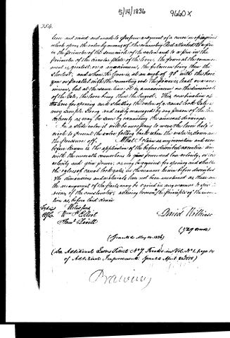
lever and raised and made to perform a segment of a curve or epicycloid which opens the valve by means of the connecting rod attached to a pin in the perimeter of the semicircle of the valve and to a pin in the perimeter of the circular plate of the lever. The force at the commencement is greatest; on a maximum, the fulcrum being then the shortest; and when the lever is at an angle of 90° with the horizontal or parallel with the connecting rod the power is least or a minimum, but at the same time it is a maximum on the dimensions of the valve, the lever being then the longest. This combination of the lever for opening and shutting the valve of a canal lock gate is very simple, strong, and easily managed by any person of the firm.
In a slide valve it will be necessary to move the lever half a circle to prevent the water falling back when the valve is down and the pressures off.
What I claim as my invention and never before known is the application of the before described eccentric lever with the movable connections to gain power and lose velocity, or vice versa, and gain power, as may be required for opening and shutting the gates of canal lock gates, in the manner herein before described. The dimensions and materials have not been mentioned as these and the arrangement of the parts may be varied in any manner to suit the views of the constructor, adhering however to the principle of the invention as before laid down.
Witnesses
Wm. G. Elliot
Sam'l Herrell
David Willins
(29 words)
(Granted May 14, 1836)
(See Additional Letters Patent No. 7. Found in Vol. 3 No. 1, page 14 of Additional Improvements. Granted April 24, 1835)
D. Willins
Published accounts: journal notice
Notice in the monthly list of patents
Journal of the Franklin Institute, new ser., vol. 18 (1836), p. 143 · View the page
379. Reed making machine.-J. A. Wilkinson, Providence, R. Island, CELESTIAL PHENOMENA, FOR SEPTEMBER, 1836. Calculated by S. C. Walker.
About this record
- Patentee
- DATAMP
- Date
- the Name and Date index of patents, DATAMP, USPTO records
- Invention
- DATAMP
- Listed in
- the Name and Date index of patents, DATAMP, USPTO records, Jim Shaw's X-patent list, the Journal of the Franklin Institute, Burke's List of Patents (1847)
- Burke's 1847 Patent Office list gives the same patent.