

Drawings and documents
National Archives restored drawings: drawing
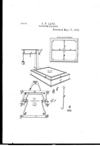
Calvin P. Ladd's Patent Drawing for a Platform Balance

National Archives, Restored Patent Drawings (Record Group 241) · Full-size scan at the National Archives · Catalog record
Show the text on the drawing Hide (50 words)
Words on the drawing as machine-read by the National Archives; not checked. Useful mainly for searching.
Scales: / 7 150 / CLASSIFICATION / 9664t / DIVICION / 9664 X / 14 / Malferm / May 17th 1636. / Underside of the Platform. / TTL / ILI / LD / ED / ma / Plan / OR / of / Top of the / combined Lievers. / To / "CO / Platfori' / o o / Uth / in / ge
USPTO scan
The patent as scanned by the USPTO
-
 Page 1
-
 Page 2
-
 Page 3


U.S. Patent and Trademark Office · Google Patents
Show the transcription Hide (659 words)
Machine transcription (LightOnOCR) of the pages as scanned by the USPTO, most of them the handwritten copies made when the records were restored after the 1836 fire. Not checked; it can misread handwriting, so compare it with the scan.
Page 1.
9664X
C. P. LADD.
PLATFORM BALANCE.
Patented May 17, 1836.
Under side of the Platform.
Top of the Platform.
Plan of combined Levers.
Page 2.
9664x
May 17, 1836
Calvin P. Laad of Saraburg, Vermont
Letters Patent.
The schedule referred to in these Letters Patent and making part of the same, containing a description in the words of the said Calvin P. Laad himself of his improvement in the platform Balance.
Be it known that I Calvin P. Laad of Saraburg in the county of Caledonia and state of Vermont, have made a new and useful improvement in the useful arts, being a machine for weighing, called "Laad's Improved Platform Balance," which is described as follows, reference being had to the annexed drawings of the same, making part of this specification.
This Balance consists of a rectangular frame A, of any convenient size and strength adapted to the purpose intended. On the top and bottom of this frame are cast iron frames B, F, C embracing this frame A, and secured to the same by screws. In the upper cast iron frame B, are left or drilled apertures to admit the screws D, to which are suspended the loops E, made of an oval figure. In these loops are suspended the levers H, G, H, by pins I projecting from the side of the levers, these levers are connected together and suspended by rings K, and pivots L, which have heads or projections to prevent the rings from slipping off. The platform upon which the weight to be weighed is placed rests upon four pivots M, projecting from the inner side of the levers; the bearings on the underside of the platform, and which rest upon the pivots M, are faced with steel. Four rods N, to keep the platform in its proper position and prevent its breaking the sides of the frame, extended from the sides of the platform to the centre of the frame, where they are attached to pins or points O, which will prevent the platform from vibrating horizontally in any direction. The levers H are brought together at P, where there is a movable pivot Q, for adjusting the levers; this pivot is attached by screws and nuts which may be adjusted by moving the bolts backward or forward, in oblong sockets in the ends of the levers as required. This pivot is suspended in a hook formed at the end of a vertical
Page 3.
May 17, 1836
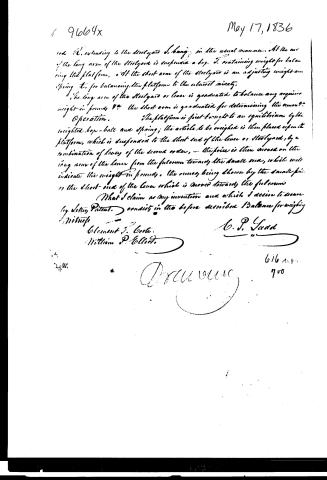
I do hereby acknowledge to the steelyard I hang in the usual manner. At the end of the long arm of the steelyard is suspended a box, T, containing weights for balancing the platform, and at the short arm of the steelyard is an adjusting weight and spring, etc., for balancing the platform to the utmost nicety.
The long arm of the steelyard or lever is graduated to balance any required weight in pounds, and the short arm is graduated for determining the ounces.
Operation. The platform is first brought to an equilibrium by the weighted box-ball and spring; the article to be weighed is then placed upon the platform, which is suspended to the short end of the lever or steelyard, by a combination of levers of the second order, the force is then moved on the long arm of the lever from the fulcrum towards the small end, which will indicate the weight in pounds, the ounces being shown by the small force on the short end of the lever which is moved towards the fulcrum.
What I claim as my invention and which I desire to secure by Letters Patent, consists in the before described Balance for weighing.
Witness
Clement J. Coote
William P. Elliott
A. P. Sudd
616 2.0
700
Published accounts: journal notice
Notice in the monthly list of patents
Journal of the Franklin Institute, new ser., vol. 18 (1836), p. 143 · View the page
360. Platform balance.-C. P. Ladd, Irasburg, Vermont,
About this record
- Patentee
- DATAMP
- Date
- the Name and Date index of patents, DATAMP, USPTO records
- Invention
- DATAMP
- Listed in
- the Name and Date index of patents, DATAMP, USPTO records, Jim Shaw's X-patent list, the Journal of the Franklin Institute, Burke's List of Patents (1847)
- Burke's 1847 Patent Office list gives the same patent.