

Drawings and documents
National Archives restored drawings: drawing
A.J. Dawley's Patent Drawing for a Steam Engine


National Archives, Restored Patent Drawings (Record Group 241) · Full-size scan at the National Archives · Catalog record
Show the text on the drawing Hide (50 words)
Words on the drawing as machine-read by the National Archives; not checked. Useful mainly for searching.
Sheet 1. 191 / STEAM Qteam Engines / ENGINES. / [150] Osoillating / 1250 / 9.672.x / All Darley / DIVIZTONT / Plate Patented 23.May 1836 / 9672X / Steam Engine / PLATE 1. / Fig.1. / tig 2. / Is / E.J.S.
Sheet 2. 121, STEAM. / I. ENGINES. / [150] Oscillating. / 9.672.1 / 2. / DIVISION. / 9672 / Fight / Tig 2 / Fig.3. / in / hit / 12
USPTO scan
The patent as scanned by the USPTO
-
 Page 1
-
 Page 2
-
 Page 3


U.S. Patent and Trademark Office · Google Patents
Show the transcription Hide (795 words)
Machine transcription (LightOnOCR) of the pages as scanned by the USPTO, most of them the handwritten copies made when the records were restored after the 1836 fire. Not checked; it can misread handwriting, so compare it with the scan.
Page 1.
9672X
A. S. Darley,
Oscillating Steam Engine.
Patented May 23, 1836.
Fig. 1.
Fig. 2.
Fig. 1.
Fig. 2.
Fig. 3.
Page 2.
9672X
May 23, 1836
Augustus W. Vauclay of Boston, Massachusetts,
Letters Patent
The schedule referred to in these Letters Patent and making part of the same containing a description in the words of the said August W. Vauclay himself of his improvement in the Steam Engine.
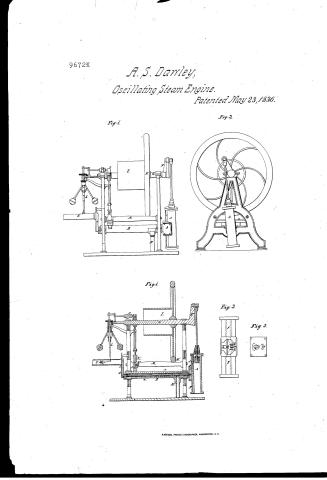
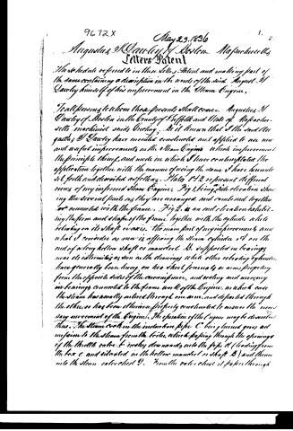
To all persons to whom these presents shall come: Augustus W. Vauclay of Boston in the County of Suffolk and State of Massachusetts machinist says Greeting. Be it known that I the said Augustus W. Vauclay have invented constructed and applied to use new and useful improvements in the Steam Engine which improvement the principle thereof, and mode in which I have contemplated the application together with the manner of using the same I have hereunto set forth and described as follows. Figs 1 & 2 represent different views of my improved Steam Engine. Fig 1, being side elevation showing the several parts as they are arranged and combined together or connected with the frame. Fig 2, is an end elevation exhibiting the form and shape of the frame together with the cylinder while revolving on its shaft or axis. The main part of my improvement and what I consider as new is affording the steam cylinder A on the end of a long hollow shaft or mandrel B, supported in bearings near its extremities as seen in the drawings while other revolving cylinders have generally been hung on two short journals or arms projecting from the opposite sides of the circumference, and resting and moving in bearings connected to the frame work of the Engine, in which case the steam has usually entered through one arm, and departed through the other, so has been of dubious properly constructed to ensure the necessary movement of the Engine. The operation of the Engine may be described thus. The steam evoked in the induction pipe C being turned gives admission to the steam from the boiler, which passing through the openings of the throttle valve b rushes downwards into the pipe d (leading from the box c and situated in the hollow mandrel or shaft B) and thence into the steam cylinder chest D. From the valve chest it passes through
Page 3.
286. 9672X May 23, 1836 2.
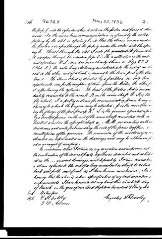
the pipe f into the cylinder when it acts on the piston and forces it down. In the mean time a communication is opened by the valve passing by the slot or opening l, so that the steam or air under the piston escapes through the pipe g under the valve into the opening h. Thence through the slot I into the mandrel D from which it escapes through the ejection pipe C. The construction of the valve and apertures K, L, M, are more clearly shown in Figs 2 & 3 (Plate 2.) the valve being stationary and attached to the end of a lever and at the other end of which is secured to the lower part of the Steam Box c. The Steam Chest is divided by a partition m into two apartments, one for the reception of steam from the Boiler, the other for it after leaving the cylinder. The head of the piston Rod is immediately connected to the crank N on the main shaft O. H is the fly wheel, I a pulley or drum for communicating power to any machinery to which the Engine may be attached, P is the eccentric acting the plunges of the force pump R. L is the governor operated upon by a bevelled pinion on the end of the main shaft connected with a bevelled wheel on the upright shaft o. M, M, are iron ties with M, M, dovetails and nuts for connecting the ends of the frame together, i, i, counterpoises of the governor. The remainder of the machinery is constructed as represented in the drawings and may be otherwise fixed or arranged if necessary.
In conclusion what I claim as my invention and improvement is the combination of the several parts together as described and exhibited in the... annexed drawings, and separately I claim connecting a steam cylinder to the end of a long mandrel or shaft to vibrate back and forth and operate as I have herein mentioned. In testimony that the above is a true specification of my said invention and improvements I have hereunto set my hand this nineteenth day of March in the year of our Lord Eighteen hundred & thirty six.
Evd. Witnesses
1836 V. H. Eddy
J. W. Adams
Augustus St. Clairley
Published accounts: journal notice
Notice in the monthly list of patents
Journal of the Franklin Institute, new ser., vol. 18 (1836), p. 143 · View the page
371. Steam engine.-A. S. Dawley, Boston, Mass.
About this record
- Patentee
- DATAMP
- Date
- the Name and Date index of patents, DATAMP, USPTO records
- Invention
- DATAMP
- Listed in
- the Name and Date index of patents, DATAMP, USPTO records, Jim Shaw's X-patent list, the Journal of the Franklin Institute, Burke's List of Patents (1847)
- Burke's 1847 Patent Office list gives the same patent.