

Drawings and documents
National Archives restored drawings: drawing
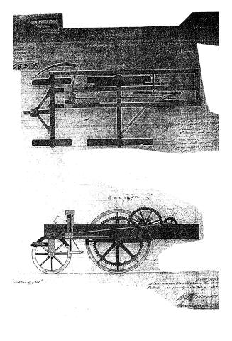
H. Allen's Patent Drawing for a Mowing Machine

National Archives, Restored Patent Drawings (Record Group 241) · Full-size scan at the National Archives · Catalog record
Show the text on the drawing Hide (117 words)
Words on the drawing as machine-read by the National Archives; not checked. Useful mainly for searching.
HARVESTERS, / Findered: / Not 25. page 153- / Mowers, / Anomalion. / Patented 2 june 1836 / $3 / HALLIN / classusication / Morring Machine / 9683.X / DIVISIOST / T2 / 9683 / plan / a -Machinery wheel a'. opposite wheel / e.2.1 C. b. Perious east from coy d 2d large of Machiner egg wheel / wheel which / -on shafh / punion with crank and Ply wheel / f. Threepences of Frame I axle h. Miding / -Frame with unight axle moved by a gitne / K. serve circular cog what l. slide m Rack / 72. seythe / Sec / to / C. / shickland belt / Patent effice June 30.9943 / Made under the direction of the communproun of / Patuls in conform by with actor 3'llarch 1837- / M.Sunorth / Communious Patent
USPTO scan
The patent as scanned by the USPTO
-
 Page 1
-
 Page 2
-
 Page 3
-
 Page 4


U.S. Patent and Trademark Office · Google Patents
Show the transcription Hide (836 words)
Machine transcription (LightOnOCR) of the pages as scanned by the USPTO, most of them the handwritten copies made when the records were restored after the 1836 fire. Not checked; it can misread handwriting, so compare it with the scan.
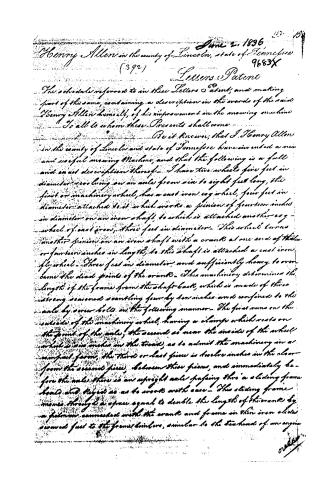
Page 2.
June 2, 1896
Henry Allen in the county of Lincoln, state of Tennessee
(392)
9683X
Letters Patent
The schedule referred to in these Letters Patent, and making part of this same, containing a description in the words of the said Henry Allen himself, of his improvement in the mowing machine.
To all to whom these Presents shall come.
Be it known, that I, Henry Allen in the county of Lincoln and state of Tennessee have invented a new and useful mowing Machine, and that the following is a full and exact description thereof. I have two wheels five feet in diameter revolving on an axle from six to eight feet long, the first or machinery wheel, has a cast iron cog wheel, four feet in diameter attached to it which works a pinion of fourteen inches in diameter on an iron shaft, to which is attached another cog-wheel of cast iron, three feet in diameter. This wheel turns another pinion on an iron shaft with a crank at one end of the same or fourteen inches in length, to this shaft is attached a cast iron fly wheel. Three feet in diameter, and sufficiently heavy to overcome the dead points of the crank. This machinery determines the length of the frame from the shaft back, which is made of three strong seasoned scantling four by ten inches and confined to the axle by corner bolts in the following manner. The first runs on the outside of the machinery wheel, having a clamp which rests on the point of the axle, the second as near the inside of the wheel which is ten inches in the tread, as to admit the machinery in a compact form, the third or last piece is twelve inches in the clear from the second piece, between these pieces, and immediately before the axle there is an upright axle passing thro' a sliding frame head and keyed as as to work with ease. This sliding frame moves through a space equal to double the length of the crank by a pinion connected with the crank and frame in thin iron slides screwed fast to the frame timbers, similar to the teeth end of an engine.
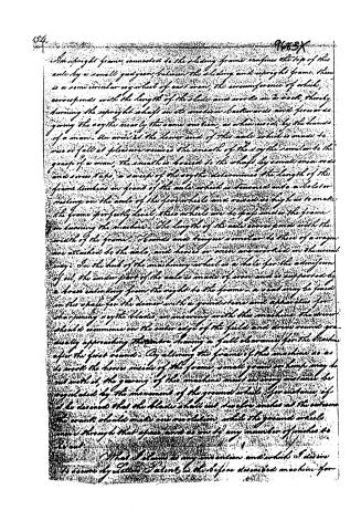
Page 3.
An upright frame, connected to the sliding frame, confines the top of this axle by a small guage, between the sliding and upright frame. There is a semi-circular cog-wheel of cast iron, the circumference of which corresponds with the length of the slide and works on a rack, thereby turning the upright shaft in its motion backwards and forwards giving the way the nearly the same motion, as when used by the hands of a man. An arm at the lower end of this axle which is made to rise or fall at pleasure receives the mouth of the way the similar to the grasp of a man, the mouth is located to the shaft by small screws and screw taps, a sweep of the way the determines the length of the frame timbers in front of the axle which is turned onto a bolster resting on the axle of the four wheels and raised as high as to make the frame perfectly level, these wheels are to pass under the frame in turning the machine. The length of the axle corresponds with the width of the frame. Boards and tongue similar to those of a wagon are attached to the axle, and horses or oxen are worked in the usual way. In the hub of the machinery wheel is a hole for the admission of oil, the under part of the axle is made of iron and is supported by a brace extending from the right to the frame. A seat may be fixed in the space for the driver with a grindstone and apparatus for sharpening way the blade, in moving with the machine, the driver should commence on the outer edge of the field and drive round gradually approaching the centre, having a full clearance for the machine after the first round. By altering the frame of this machine so as to work the horses inside of the frame, small grain or hemp may be cut with it, the gearing of this machine must in every instance be regulated by the movement of the ground wheel. For instance, if it be desired that the blade shall cut twelve inches at the extreme the crank should make one revolution, while the ground wheel moves through that space and so on to any number of inches to be cut.
That I claim as my invention and which I desire to secure by Letters Patent is the before described machine for
Page 4.
9683X
mowing hay and cutting grass - H. Allen
(Wilney)
(H. P. Blixt)
(J. Watson)
Drawing made
Ex. 1
119.6
About this record
- Patentee
- DATAMP
- Date
- the Name and Date index of patents, DATAMP, USPTO records
- Invention
- DATAMP
- Listed in
- the Name and Date index of patents, DATAMP, USPTO records, Jim Shaw's X-patent list, Burke's List of Patents (1847)
- Burke's 1847 Patent Office list gives the same patent.