

Drawings and documents
National Archives restored drawings: drawing
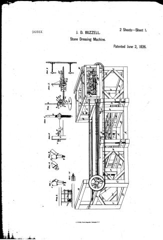
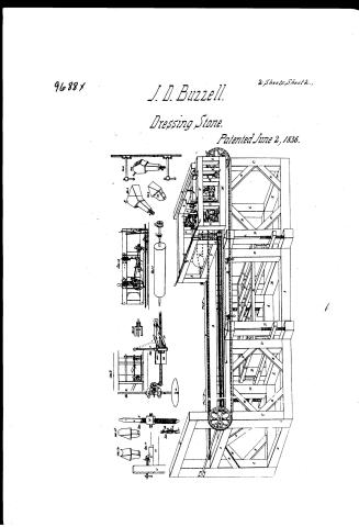
Dr. John D. Buzzell's Patent Drawing for a Stone Dressing Machine

National Archives, Restored Patent Drawings (Record Group 241) · Full-size scan at the National Archives · Catalog record
Show the text on the drawing Hide (53 words)
Words on the drawing as machine-read by the National Archives; not checked. Useful mainly for searching.
ley / Patented June 2. / 8 3 6. / 9688X / DIV ISION. / See. 1 / Sec. 2 / Sec. 3 / Sec 4 / Sec. / 5. / Sec / Sec 7. / Sec.8. / OF / 33 / Sec 9. / 512 / bb / Sec. 10. / Flone dressins Michael BY / INVENTED / Ar. Jobn II / of / Cape Elizabeth, Maine. / Patented June 2?1836 / Lifhog: P.Hoas) Washington / .M
USPTO scan
The patent as scanned by the USPTO
-
 Page 1
-
 Page 2
-
 Page 3
-
 Page 4
-
 Page 5


U.S. Patent and Trademark Office · Google Patents
Show the transcription Hide (1,145 words)
Machine transcription (LightOnOCR) of the pages as scanned by the USPTO, most of them the handwritten copies made when the records were restored after the 1836 fire. Not checked; it can misread handwriting, so compare it with the scan.
Page 1.
9688X
J. D. BUZZELL.
Stone Dressing Machine.
2 Sheets—Sheet 1.
Patented June 2, 1836.
N. PETERS, Photo-Lithographer, Washington, D. C.
Page 2.
96887
J. D. Buzzell.
Dressing Stone.
Patented June 2, 1836.
2 Sheets, Sheet 2.
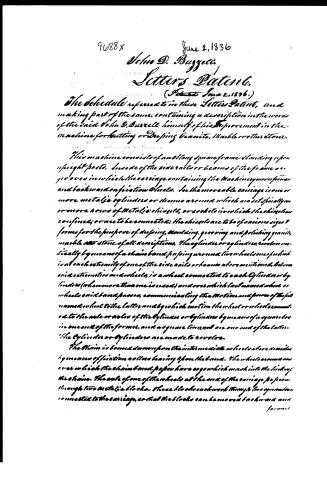
Page 3.
9688X
June 2, 1836
John D. Burrell
Letters Patent.
(Patented June 2, 1836.)
The Schedule referred to in these Letters Patent, and making part of the same, containing a description in the words of the said John D. Burrell himself of his Improvement in the machine for cutting or deeping granite, Marble or other stone.
This machine consists of a double square frame clinching upon upright posts. Under of the side rails or beams of the frame are grooves in which the carriage containing the machine gears for forward and backward motion on friction wheels. In the movable carriage is one or more metallic cylinders or drums around which are set specially grooved or more rows of metallic chisels, or sockets in which the chisels are confined; or one to be connected; the chisels are to be of various sizes & forms for the purpose of deeping, moulding, grooving and polishing granite, marble & stone of all descriptions. The cylinders or cylinders revolve vertically by means of a chain band passing around two wheels one of which is at each extremity of one of the side rails or beams above mentioned. Below said extremities and wheels, is a wheel connected to each Cylinder or by lines (when more than one is used) and over which last named wheel or wheels said band passes, communicating the motion and power of the first named wheel to the latter, and by which motion the wheel or wheels connected to the axle or axles of the cylinders or cylinders by means of a square box in one end of the frames, and a square thread on one end of the latter. The Cylinder or Cylinders are made to revolve.
The Chain is bound down upon the intermediate wheels above mentioned by means of friction rollers bearing upon the band. The wheels are made over which the chain band passes have a groove which mesh into the links of the chain. The axle of one of the wheels at the end of the carriage passes through two metallic blocks. These blocks each work through two grooves, connected to the carriage, so that the blocks can be moved backward and forward.
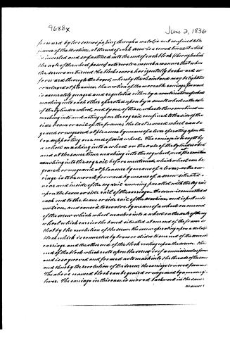
Page 4.
June 2, 1836
forward by the screw passing through a metallic rod confined to the frame of the machine. At the end of each screw is a round tin nut which is inverted and so fastened into the end of each block (through which the axle of the wheel passes) as to revolve in such a manner that when the screw is turned, the blocks move horizontally backward or forward through the boxes; whereby the chain bands may be tightened or relaxed at pleasure. The motion of the movable carriage forward is accurately gauged and regulated either by a combination of wheels meshing into each other operated upon by a small wheel on the axle of the cylinder wheel, and by one of those wheels thus combined meshing into and acting upon the cog rail confined to the side of the side beam or rail of the frame; the last named wheel can be geared or ungeared at pleasure by means of a lever operating upon the box supporting one end of said wheels. The carriage is brought by a wheel meshing into a wheel on the axle of the cylinder wheel and at the same time meshing into the cog wheel, and the same wheel meshing into the cog rail before mentioned, which wheel can be geared or ungeared at pleasure by means of a lever; or the carriage is to be moved forward by means of a screw situated near and inside of the cog rail running parallel with the cog rail upon the beam or side rail of the carriage. The screw is connected at each end to the beam or side rail of the machine, and is put into motion and caused to revolve by means of a wheel on one end of the screw which wheel meshes into a wheel on the axle of the cylinder wheel which carries the band situated at one end of the frame so that by the revolution of the screw, the screw operating upon a metallic block which is connected by levers or slides to one end of the movable carriage and the other end of the block resting upon the screw. This end of the block which rests upon the screw is of a conical or tapering and is so grooved and formed as to mesh into the threads of the screw and thus by the revolution of the screw, the carriage is moved forward. The above named block can be geared or ungeared by means of a lever. The carriage in this case is moved backward in the same manner.
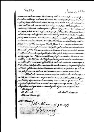
Page 5.
June 2, 1836
manner, as is moved backwards, when moved forwards by a combination of wheels. Between the rails of the frame is a bed or platform to hold the stone or any other article to be operated upon, over which the movable carriage is to pass. This platform is made of timber with no bars forming gates work over laid with metallic plate and is supported by upright posts with round heads at each end. The upper ends connected by sockets to the timbers of the platform, and the lower ends resting in sockets confined to the transverse bars situated below the platform and extending outside the frame of the carriage. The platform is moved upwards and downwards by means of screws working through nuts connected to or near the ends of the transverse bars, which nuts move on their centers for the purpose of varying the position of the platform as circumstances may require. The screws stand perpendicular. The lower ends resting in metallic sockets passing through the nuts described above, and the upper ends are supported by holes inverted in or connected to posts, which posts are connected to the beams of the frame and project outside of the machine, the screws are turned by levers by which the platform is raised or lowered as occasion demands.
What I claim as new and for which I ask Letters Patent is the particular arrangement and combination of the cutting and polishing cylinders and Belts, the method of raising and regulating the stone, and the arrangement of machinery for moving the carriage and revolving the cylinders or cylinders.
Witnesses
W. Burke
Mason, Mass.
John C. Bracewell
1125 words
(Rec'd & Recorded June 22, 1837)
O. J. A.
Published accounts: journal notice
Notice in the monthly list of patents
Journal of the Franklin Institute, new ser., vol. 18 (1836), p. 214 · View the page
385. Granite dressing machine.-J. D. Buzzell, Cape Elizabeth, Maine,
About this record
- Patentee
- DATAMP
- Date
- the Name and Date index of patents, DATAMP, USPTO records
- Invention
- DATAMP
- Listed in
- the Name and Date index of patents, DATAMP, USPTO records, Jim Shaw's X-patent list, the Journal of the Franklin Institute, Burke's List of Patents (1847)
- Burke's 1847 Patent Office list gives the same patent.