

Drawings and documents
National Archives restored drawings: drawing
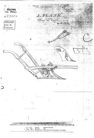
J. Plank's Patent Drawing for an Improved Plough

National Archives, Restored Patent Drawings (Record Group 241) · Full-size scan at the National Archives · Catalog record
Show the text on the drawing Hide (34 words)
Words on the drawing as machine-read by the National Archives; not checked. Useful mainly for searching.
Intered / 97. PLOWS. / [114] Plows. / 49701x / all PLANK / CLASSIFICATION / " Tlugh / Patented June 2. 1836. / 9701 x / PIVISION. / I G / Hift / Ii / (o
USPTO scan
The patent as scanned by the USPTO
-
 Page 1
-
 Page 2
-
 Page 3


U.S. Patent and Trademark Office · Google Patents
Show the transcription Hide (855 words)
Machine transcription (LightOnOCR) of the pages as scanned by the USPTO, most of them the handwritten copies made when the records were restored after the 1836 fire. Not checked; it can misread handwriting, so compare it with the scan.
Page 1.
7. PLOWS
[114] Plows.
49701X
CLASSIFICATION
701X
VISION.
Entered
J. PLANK
Simp Plough
6-2-1836
Patented June 2, 1836

METRIC SYSTEM
General Services Administration
National Archives and Records Service
Washington, DC 20408
Page 2.
June 2, 1836
Jacob Plank, of Carlisle, Penna. 9701X
Letters Patent.
The Schedule refers to in their Letters Patent, and making part of the same, containing a description in the words of the said Jacob Plank himself, of his improvement in the Plough.
Be it known that I, Jacob Plank, of near Carlisle, in the County of Cumberland, and State of Pennsylvania, have made a new and useful improvement in the Plough: which is described as follows, reference being had to the annexed drawings of the same, making part of this specification —
On a mould board A, about two feet two inches long, more or less, as may be required, there is a wing B, cast with said mould board, running nearly perpendicular along the inner side of the same, at a distance of 16½ inches from the front point of the mould board on the upper edge of the same, & about 10 inches from the same point on the under edge. This wing is about 3½ inches broad and half an inch thick, & stands out from said mould board inclining to the point of the same, so as to form an acute angle with the front part of the mould board. There is an iron brace C, also cast with the mould board 5⅞ of an inch in diameter and 2½ inches long, connected with the wing & the mould board. There are two holes in said wing for screws to fasten the same to the sheath D. The mould board extends over the side piece on the right hand side of the mould board and connects with the side piece E, by a joint on the inner edge of the mould board, commencing two inches from the front point of said mould board and extending up along said inner edge six inches and three quarters. The side piece is made of cast iron 16½ inches long on the lower edge, 12½ inches on the upper edge, and 5½ inches high. There are two holes near the centre of the side piece to fasten it with screws to the sheath. This side piece fits neatly into the joint of the mould board, and has a wing F, cast with it and forming a part of it of a triangular shape, the base and perpendicular sides of which are each 3⅞ inches in length & the hypotenuse 6 inches. This wing is on the upper side of the side piece next
Page 3.
246
9701X
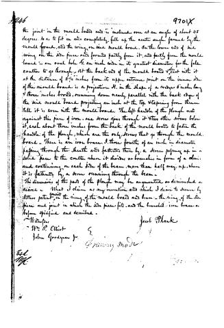
the joint in the mould board and is inclined over at an angle of about 45 degrees, so as to fit in and completely fill up the acute angle formed by the mould board, and the wing on said mould board. On the lower end of said wing on the side piece are formed partly from it, and partly from the mould board is an oval hole 6. an inch wide in its greatest diameter for the fella coulter to go through. At the back end of the mould board 4" cast with it at the distance of 2 1/2 inches from its upper extreme point on the inner side of the mould board is a projection H. in the shape of a wedge 6 inches long 4 three inches broad, running down nearly parallel with the back edge of the said mould board projecting an inch at the top tapering from three till it is even with the mould board. The left handle of the plough rests against this piece of iron. one screw goes through it 4 two other screws below it, each about three inches from the back of the mould board to fasten the handle of the plough, which are the only screws that go through the mould board. There is an iron brace I. three fourths of an inch in diameter passing through the sheath and fastened there by a screw passing up in a solid piece to the coulter when it divides or branches in form of a clevis and continuing on each side of the beam more than half way up, when it is fastened by a screw running through the beam.
The dimensions of the parts of the plough may be augmented or diminished as desired. What I claim as my invention and which I desire to secure by letters patent, is the wing of the mould board and brace, the wing of the side piece and joint in which the side piece fits, and the branched iron brace as before specified and described.
Witnesses
Wm. P. Elliot
John Gordyean Jr.
Jacob Plank
Drawing Made
E.L.
H.C.
Published accounts: journal notice
Notice in the monthly list of patents
Journal of the Franklin Institute, new ser., vol. 18 (1836), p. 214 · View the page
383. Plough.-Jacob Plank, Carlisle, Penn.
About this record
- Patentee
- DATAMP
- Date
- the Name and Date index of patents, DATAMP, USPTO records
- Invention
- DATAMP
- Listed in
- the Name and Date index of patents, DATAMP, USPTO records, Jim Shaw's X-patent list, the Journal of the Franklin Institute, Burke's List of Patents (1847)
- Burke's 1847 Patent Office list gives the same patent.