

Drawings and documents
National Archives restored drawings: drawing
Edward Whitfield's Patent Drawing for a Pump

National Archives, Restored Patent Drawings (Record Group 241) · Full-size scan at the National Archives · Catalog record
Show the text on the drawing Hide (39 words)
Words on the drawing as machine-read by the National Archives; not checked. Useful mainly for searching.
EDWARD / 9703. Xicker / DIVILIC / Class 103-PUMPS. / 103-PUMPS. / Diaphragm. / PUMP. Satested 2 free 1536, (Patented / 97033 / Diaphragm. / Giass 103-PUMPS / Pat Due n / Diaphragm. / 1834 / Fig .5 / Class 103-PUMPS / Diaphragm / Fig 4
USPTO scan
The patent as scanned by the USPTO
-
 Page 1
-
 Page 2
-
 Page 3
-
 Page 4


U.S. Patent and Trademark Office · Google Patents
Show the transcription Hide (1,074 words)
Machine transcription (LightOnOCR) of the pages as scanned by the USPTO, most of them the handwritten copies made when the records were restored after the 1836 fire. Not checked; it can misread handwriting, so compare it with the scan.
Page 1.
9703X
E. Whitfield,
Pump Bellows
Patented June 2, 1836.

Page 2.
June 2, 1836
Edward Whitfield, of New York 9703X
Letter Patent
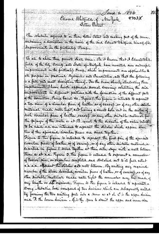
The Schedule referred to in these Letter Patent and making part of the same, containing a description in the words of the said Edward Whitfield himself, of his Improvement in the frictionless Pump.
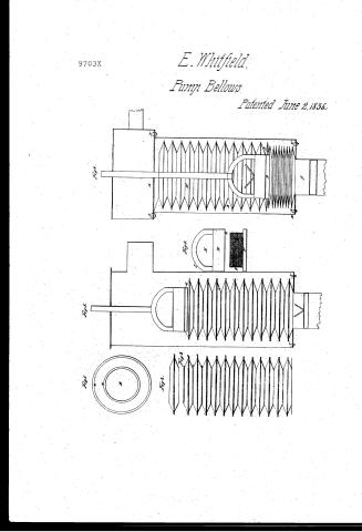
To all to whom these presents shall come: Be it known that I Edward Whitfield of the City, County, and State of New York have invented new and useful improvements in the frictionless Pump, which improvements are applicable to all purposes in practical Hydraulics and Pneumatics, and that the following is a full and exact description thereof. For the more clearly illustrating these improvements I have hereto appended several drawings exhibiting the said improvements in different positions, with the formation of the different parts of the connector, Pump barrel, &c. Figure 1. This figure is intended to represent a Top view of a circular piece of leather, or of canvas, or of any other suitable material made water tight, and having a round hole cut in the centre of such circular piece of leather, canvas, or any other suitable material for the passage of the water as at B. equal to the diameter of the valve intended to be used and are intended to represent the stitches which appear when two of the aforesaid circular pieces are driven together.
Figure 2. This figure is intended to represent the first pair of the aforesaid circular pieces of leather, or of canvas, or of any other suitable material, as described in figure 1. joined together at their outer edges with a well between them as at a.a. Figure 3. This figure is intended to represent a connector of twelve pairs, or chambers completed, and stretched out to its full extent a.a.a.a. represent the stitches and wells between. By uniting any required number of the above described circular pieces of leather, or of canvas, or of any other suitable material made water tight the connector may be made of any length or size required. Figure 4. This figure is intended to represent a strong Metallic box composed of two divisions, which are subsequently united by forming the two uniting parts into a seam as at d. C. is the upper division and F. the lower division. G. is the space to admit the upper and inner rim
Page 3.
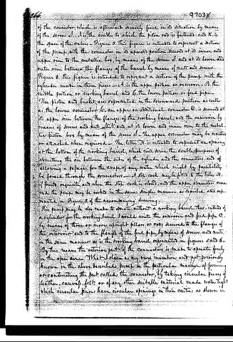
of the connector, which is afterwards securely fixed in its situation by means of the screw J. J is the cradle to which the piston rod is fastened, and K is the space of the valves - Figure 5. This figure is intended to represent a section of the pump, with the connector in its upward position, secured at its inner and upper rim to the metallic box, by means of the screw J, and at its lower and outer rim between the flanges of the barrel by means of nuts and screws.
Figure 6. This figure is intended to represent a section of the pump with the cylinder made in three pieces - A is the upper portion or reservoir - B the middle portion or working barrel, and C the lower portion or feed pipe. The piston and bucket are represented in the downward position as well as the lower connector K. An upper or additional connector D is secured at its upper rim between the flanges of the working barrel, and the reservoir by means of screws and nuts M, and at its lower and inner rim to the metallic piston box by means of the screw J. The upper connector may be removed or attached when required. The letter H is intended to represent an opening at the bottom of the working barrel, which will serve the double purpose of admitting the air between the sides of the cylinder and the connectors, and of allowing a passage for the escape of any water which might by possibility be forced through the connectors. A stop cock may be fitted to this hole H, if found requisite, and when the stop cock is closed, and the upper connector removed the pump may be worked in the same simple manner as described and represented in Figure 5 of the accompanying drawing.
This pump may be also made to operate without a working barrel. Thus, instead of a cylinder for the working barrel, I would unite the reservoir and feed pipe C, by means of three or more upright pillars or rods, secured to the flanges of the reservoir and to the flange of the feed pipe, by means of screws and nuts, in the same manner as is the working barrel represented in figures 5 and 6. By this means, the exterior part of the connector is made to operate freely in the open air. What I claim as my own invention and not previously known in the above described pump is the particular manner of forming or constructing the part called the connector, by taking circular pieces of leather, canvas, felt, or of any other suitable material made water tight, which circular pieces have circular openings in their centre, as shown in
Page 4.
267
9703X
267
figure 1. in the accompanying drawing, and uniting any required number
of them, by sawing, or cementing, or fastening them together in the manner
described; by which means this part of the apparatus is rendered stronger and
its action more perfect than by any of the methods hitherto adapted.
And I also claim the particular manner of attaching an additional con-
nector to the pump, between the flanges of the reservoir, and the flanges of
the working barrel by means of screws and nuts, and to the metallic pis-
ton box, by means of the screw 6, in the same manner as described in figure
6 of the accompanying drawing, by which additional connector so attached,
the working barrel of the pump is kept free from sand, soil or any other sub-
stance, or by substituting upright pillars or rods for a working barrel, the
connectors are made to operate more freely, and with less friction, than
by any of the methods hitherto known or used.
Witnesses
John Johnson
W. D. Brayton
Ed. Whitfield
New York 22 April 1856
Drawings
1078 11 82
Exd
11/16
Published accounts: journal notice
Notice in the monthly list of patents
Journal of the Franklin Institute, new ser., vol. 18 (1836), p. 215 · View the page
394. Pump, frictionless. Edward Whitfield, N. Y.
About this record
- Patentee
- DATAMP
- Date
- the Name and Date index of patents, DATAMP, USPTO records
- Invention
- DATAMP
- Listed in
- the Name and Date index of patents, DATAMP, USPTO records, Jim Shaw's X-patent list, the Journal of the Franklin Institute, Burke's List of Patents (1847)
- Burke's 1847 Patent Office list gives the same patent.