

Drawings and documents
USPTO scan
The patent as scanned by the USPTO
-
 Page 1
-
 Page 2
-
 Page 3
-
 Page 4


U.S. Patent and Trademark Office · Google Patents
Show the transcription Hide (1,392 words)
Machine transcription (LightOnOCR) of the pages as scanned by the USPTO, most of them the handwritten copies made when the records were restored after the 1836 fire. Not checked; it can misread handwriting, so compare it with the scan.
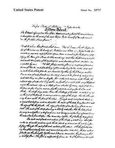
Page 2.
United States Patent
Patent No.: X9717
Nefus Porter of Belleville, Massachusetts
Letters Patent.
The Schedule of and to this Letters Patent and making part of the same, containing a description in the words of the said Nefus Porter himself of his improvement "in the Portable Horse Fence."
To all to whom these presents shall come, I, Nefus Porter, of Belleville, in the County of Middlesex and State of Massachusetts, have invented a new and useful Portable Horse Fence or machine for the purpose of applying the Fence of a Horse to this machinery, and that the following is a full and exact description of the construction and operation of said machine as invented by me.
A flat floor (or endless floor) is composed of wooden pieces of plank, each plank being eighteen inches long, twelve inches wide and one inch thick, which planks are connected together by the following method:
On one side of each plank are two slats secured to the plank by nails or screws, each slat being one foot in length, three inches wide and one inch thick. The outward edge of each slat being within one fourth of an inch of the end of the plank, and to this outward edge is a strap of iron attached by means, each strap being thirteen inches long, one and one fourth inch wide and one fourth of an inch thick. The straps being wider than the thickness of the slat, a rabbet is cut in the end of the plank to accommodate one edge of the strap, that the other edge may be even with the face of the slat. Through each end of each strap is a round hole half an inch in diameter, the center of the hole being parallel with the edges of the plank. The edges of each two planks being placed in contact, (the ends of the straps passing a little by each other that the holes of each two may come together) a half inch iron rod twenty-one inches long is passed through the ends of each four straps; thus connecting together the planks by hinge joints.
On each end of each rod outside of the straps, is a cast iron wheel four inches in diameter and one inch thick which is secured on the rod by a pin passing through the end of the rod outside of the wheel. All the planks having been placed side by side and connected as above described, the two outside planks are then brought together and likewise connected, thus forming a bell or endless floor. This floor is supported by frames as described.
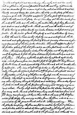
Page 3.
United States Patent
Patent No.: X9717
Two dills each eight feet and six inches long, three inches wide, and two inches thick are placed on the ground parallel to each other and being eighteen inches apart are connected by two iron rods which are turned to each dill. Directly over and twenty-two inches above the dills are two plates of the same dimensions as the dills. Each plate is supported by three posts which are turned both to the dills and to the plates, two of them being set thirteen inches from the ends of the dills and the other in the center, these posts being four inches wide and one and a half inches thick, are set near the outward end of the dills leaving a space twenty-one inches between each post and its opposite. To the inside of each three posts a nail is attached by screws or bolts; the nail is three inches deep by one and a half inch thick and each end after passing the post is turned emerging downwardly forming a semicircle of thirteen inches diameter. These nails support a part of the friction wheels of the belt floor while another part rests on the dills below. The nails are fixed five inches below the plates and the length of them must be sufficient to fill the space between the friction wheels on each side of the floor. The frame is further supported by a plank eight inches wide which passes from one center post to its opposite being turned by double turns to each immediately below the nails which are also thus by supported. An iron shaft thirty inches in length passes horizontally through the opposite posts at one end of the frame at a point central to the motion of the parts of the floor as they pass over the inner ends of the nails. This shaft is one inch and a half square, being rounded iron where it passes through the posts and extending three inches beyond the posts on each side for the purpose of receiving and carrying a gear or hand wheel. On this shaft inside of the posts are two sliders consisting of four arms each, the ends of which arms being one foot distant from each other having corresponding notches on them taken to the ends of the belt floor inside of the straps thus receiving motion from the floor, which is communicated by the gear and wheel to other machinery. When the planks composing the floor are put in motion by the feet of the horse each friction wheel in which it turns after rolling the length of the rail descends and rolls back on the dill to the forward end, where it rises
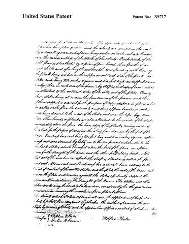
Page 4.
United States Patent
Patent No.: X9717
...occupies its place on the rails. The upper end of each rail is set with a thin plate of iron and the wheels are guided on the rails by a small square rod of iron being nailed on each rail also bending over the corners outside of the tracks of the wheels. Each track of the bell floor is sheathed by a piece of pine board three-fourths of an inch thick and of a length and breadth corresponding with those of the plank being nailed on the upper or outward side of the plank. Six states each being two inches square and six feet high are supported vertically (three on each side of the frame) by staples or straps of iron, which are attached to the outward sides of the sides and of the plates. Being these states being at or near the four corners of the frame each three of them support a side rail for the purpose of keeping the horse in place, while he walks on the floor. The side rails consisting of pine boards six inches wide being secured to the inside of the states and near the tops by screws. Two other boards or planks are also attached to the inside of the states immediately above the floor. The lower edges of the planks coming inside of the wheels for the purpose of securing the wheels from damage by the feet of the horse. Two cross bars each being two feet long and two inches square extend across and are secured by bolts one to the two forward and the other to the two back states about three feet above the level of the floor, one of these serves for the draught of the horse and the other for holding back. Note that one of the machines in which the shaft is situated is called the forward end. If one each end of each cross bar a small brace extends to the point of contact of the center states, and the plate, the end of the brace, resting on the plate and leaning against the states, officially supports the upper work in sustaining the draught of the horse. The states and other upper works may be readily taken down occasionally for the purpose of convenience in moving the machine from place to place.
The device which I claim as my invention are: the application of the four states which lie bell floor, the kind of planks, the method of securing the same to the floor by means of bolts and the application of spikes instead of wheels, etc.
Inventors:
- Stephen J. Potee
- Nathan A. Linnace
Assignee:
- Nathan Potee
Page 419
Published accounts: journal notice
Notice in the monthly list of patents
Journal of the Franklin Institute, new ser., vol. 18 (1836), p. 215 · View the page
411. Horse power.-Rufus Porter, Bellerica, Mass.
DATAMP: illustration
Illustrations from DATAMP
DATAMP (Directory of American Tool and Machinery Patents), via the Internet Archive · Archived DATAMP page
About this record
- Patentee
- DATAMP
- Date
- the Name and Date index of patents, DATAMP, USPTO records
- Invention
- DATAMP
- Listed in
- the Name and Date index of patents, DATAMP, USPTO records, Jim Shaw's X-patent list, the Journal of the Franklin Institute, Burke's List of Patents (1847)
- Burke's 1847 Patent Office list gives the same patent.