

Drawings and documents
National Archives restored drawings: drawing
Christian Knisely's Patent Drawing for an Improvement in the Making and Cording of Bedsteads

National Archives, Restored Patent Drawings (Record Group 241) · Full-size scan at the National Archives · Catalog record
Show the text on the drawing Hide (22 words)
Words on the drawing as machine-read by the National Archives; not checked. Useful mainly for searching.
oils / 20 / CP / to / of / of / VR
USPTO scan
The patent as scanned by the USPTO
-
 Page 1
-
 Page 2
-
 Page 3
-
 Page 4
-
 Page 5
-
 Page 6


U.S. Patent and Trademark Office · Google Patents
Show the transcription Hide (2,158 words)
Machine transcription (LightOnOCR) of the pages as scanned by the USPTO, most of them the handwritten copies made when the records were restored after the 1836 fire. Not checked; it can misread handwriting, so compare it with the scan.
Page 1.
No Printed Specification Available
9734X
C. Knisely,
Cording Bedsteads,
Patented June 16, 1836.

Page 2.
X 9734
June 16, 1836
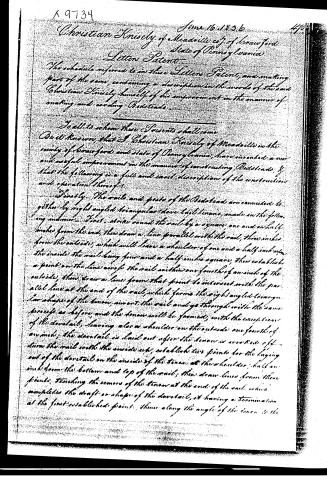
Christian Knisely of Meadville co. of Crawford State of Pennsylvania
Letters Patent
The schedule referred to in these Letters Patent, and making part of the same, containing a description in the words of the said Christian Knisely himself of his improvement in the manner of making and cording Bedsteads.
To all to whom these Presents shall come
Obe it known, that I Christian Knisely of Meadville in the county of Crawford and state of Pennsylvania, have invented a new and useful improvement in the manner of constructing Bedsteads, & that the following is a full and exact description of the construction and operation thereof.
Firstly. The rails and posts of the Bedstead are connected together by right angled triangular dovetail tenons, made in the following manner. First. strike round the rail by a square one and a half inches from the end, then draw a line parallel with the rail, three inches from the outside, which will leave a shoulder of one and a half inch on the inside the rail being four and a half inches square, then establish a point on the line across the rail within one fourth of an inch of the outside, then draw a line from that point to intersect with the parallel line at the end of the rail, which forms the right angled triangular shape of the tenon, insert the rail and go through with the same process as before, and the tenon will be formed, with the exception of the dovetail, leaving also a shoulder on the outside one fourth of an inch; the dovetail is laid out after the tenon is worked off. Turn the rail with the inside up, establish two points for the laying out of the dovetail on the inside of the tenon at the shoulder, half an inch from the bottom and top of the rail; then draw lines from these points, touching the corners of the tenon at the end of the rail, which completes the draft or shape of the dovetail, it having a termination at the first established point, thence along the angle of the tenon to the
Page 3.
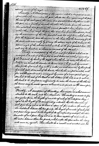
extreme corner of the angle.
Secondly, A Description of the markers, which is trapezoid in its form when the linen enters the foot. Divide two lines across the foot the size of the sail space; then draw two parallel lines lengthwise with the foot, one a fourth of an inch; the other three inches from the outside then establish two points on the second parallel line, half an inch within these lines across the foot, then draw lines from these points touching the intersection of the other parallel and two cross lines, which will complete the trapezoid, trim the excess in the shape that the linen may fit, the linen will enter easily by placing the extreme angle of the linen, at the extreme angle of the marker which will be at the first parallel line. The sail may be bound on, as shown on one end of the Model.
Thirdly, a description of the head and foot boards which are so arranged as to admit of being put on and taken out, without unsewing the Bidshead, by lashing the foot where the boards enter, the bushes or rivets are turned the diameter to be one and a half inch, by one and three fourths of an inch long, with a socket one inch diameter, by three fourths of an inch deep, at one end of the boards, these bushes are put in solid, with glue and the opposite end is arranged by means of a wire spiral spring attached to the end of the tusk at the bottom of the hole, so as to admit, the bush to be forced in sufficiently to enter the linen at the other end the linen may be made square or round and operate on the same principle.
Fourthly, A description of the sailing, how made, in what manner attached to the sails, and how strained. The sailing is made in four triangular pieces, the length of one side of each of the side pieces being equal to the length of its corresponding side of the sail, the other two sides of each piece being cut so as to leave a space of five inches in the centre of the headboard between the two points, the length of one side of each of the end pieces being equal to the length of its corresponding end of the sail, the other two sides of each piece being cut so as to leave a space of seven inches in the centre between these two points, which makes the space where the lacing cords come in, equal. There should be a small cord worked into the
Page 4.
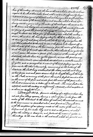
them of the sacking all around the hem on the side which is attached to the sail requires to be about three inches broad, with a cord in it sufficiently large to prevent its drawing out of the sail, each sail having a hole perforated from end to end inside of the hem, half an inch diameter, which is bored after having sawed a groove along the centre of the sail upon the inside as low as the hem, and having run an instrument through the saw cut to make an opening to guide the point of the auger, the saw cut must be large enough to admit two thicknesses of the sacking into which the sacking is drawn, the cord on the hem passing along in the hole, which prevents its drawing out, each piece, however, should be cut long enough on the side that is attached to the sail, to admit the points to be slipped off, so that the ends of the cord on the hem running from the centre of the bedshead touch the ends of the sails upon the inside, there should be an eyelet hole at each corner, the corners or points of the end pieces at the centre of the bedshead, should have two eyelets opposite, as near the point as may be, the intermediate space should be divided into a suitable number of eyelets and so arranged as to admit of the cord passing regularly from one to the other alternately, commencing at the centre of the bedshead, the sail being stationed at the centre, and the cord being in two pieces, and each piece drawn half its length through the arbor in the sail, on arriving at the foot, the cord is passed round a hook in the corner of the foot and made fast, the corner of the foot where the hook is screwed on, is taken off to the rails. The second sail is then applied, until the sacking is sufficiently strained, which completes it as shown on draft No. 1.
Draft No. 2. presents a slatting of a different shape being cut into four oblong squares, leaving a space of four inches from the centre of the bedshead to the centre of each rail, the siderails are made in the same manner as described above, and found on Draft No. 1, with the exception of an opening made at the centre of the sail, say half an inch by four inches long and as deep as the groove, at which place the sacking is drawn in, and fastened by means of eyelets in the sacking, to the iron hooks in the end rails which are grooved out.
Page 5.
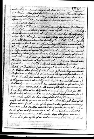
with a half round, and along it the hooks screwed in so as to come out but little more than flush with the inside of the rail. This method of arrangement will permit the packing to be put on, and taken out without separating the bedstead; it is laced in the same manner as the other, commencing at the centre.
Sixthly, a Description of the hooks, with pulleys on. The Hook may be made of wire, one fourth of an inch in diameter, the end to receive the pully turned up at a right angle, three fourths of an inch long, the pully being a little less in thickness so as to admit of being inserted slightly after being put on; the diameter about three fourths of an inch; these hooks and pulleys are designed for Bedsteads without packing, they are screwed in along the centre of the rails upon the inside, the rails being grooved out, with a half round as shown on Draft No. 2, each rail should have an odd number of hooks, the odd hook to be placed at the centre of the rail so that the cords proceeding from the Jack, which is also stationed at the centre, will run at right angles when corded and the ends made fast at the corners, the Jack is applied until sufficiently strained.
Seventhly, A Description of the straining Jack and directions how to make it. Take a block four by five inches and eight inches long, and number the four sides as follows: 1, for instance is the topside five inches 2 is the side for the wheel, four inches across 3, the underside, five inches wide 4, the opposite side to the wheel, four inches; strike round the centre of the block by a square, establish two opposite points on the centre of the block on sides No. 2 and 4, for the centre of the arbor, on side No. 2 bore a hole, three and a half inches diameter, one inch deep for the tooth wheel, then reduce it to one and a fourth inch diameter for the arbor on the wheel, and bore through the block, then draw a circle across side No. 2, two and one sixteenth inch at the right hand of the former circle for the centre of the spiral arbor, square or divide across sides No. 1 and 3. On this establish two opposite points, eleven and a fourth of an inch from side No. 2, then bore a hole from side No. 3 one inch in diameter and three inches deep, then from side No. 1 bore a hole five eighths of an inch diameter into the other, for the nut.
Page 6.
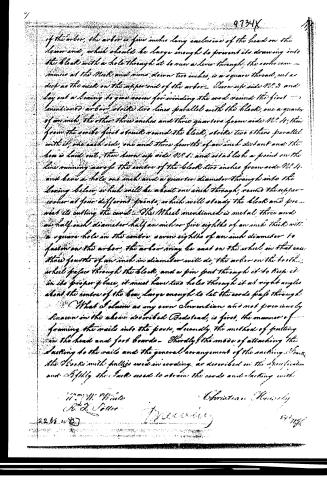
of the arbor, the arbor is five inches long exclusive of the head on the lower end, which should be large enough to prevent its drawing into the block with a hole through it to run a lever through. The arbor commences at the neck and runs down two inches, is a square thread, cut as deep as the neck on the upper end of the arbor. Turn up side N. 9 and lay out a bearing to give room for winding the cord round the first mentioned arbor, strike two lines parallel with the block, one a quarter of an inch, the other three inches and three quarters from side N. 11; then from the arbor first struck round the block, strike two others parallel with it, one each side, one and three fourths of an inch distant and the line is laid out, then turn up side N. 1 and establish a point on the line running across the centre of the block two inches from side N. 11 and bore a hole one inch and a quarter diameter through into the bearing below, which will be about one inch through, round the upper corner at four different points, which will steady the block and prevent its cutting the cord. The Wheel mentioned is metal three and one half inch diameter half an inch or five eighths of an inch thick with a square hole in the centre, seven eighths of an inch diameter to fasten on the arbor, the arbor may be cast on the wheel in that case three fourths of an inch in diameter will do; the arbor on the tooth wheel passes through the block, and a pin put through it to keep it in its proper place, it must have two holes through it at right angles about the centre of the box large enough to let the cords pass through.
What I claim as my own Invention and not previously known on the above described Bedstead, is first, the manner of framing the rails into the posts, secondly, the method of fastening on the head and foot boards. Thirdly, the mode of attaching the slatting to the rails and the general arrangement of the sashing. Fourth, the blocks with pulleys used in winding, as described on the Specification and Fifthly, the fasts used to strain the cords and slatting with.
Henry W. White
R. J. Collier
Christian University
2268 11/83
9734X
14
2268 11/83
9734X
14
Published accounts: journal notice
Notice in the monthly list of patents
Journal of the Franklin Institute, new ser., vol. 18 (1836), p. 215 · View the page
417. Bedsteads. Christian Knisly, Meadville, Penn.
About this record
- Patentee
- DATAMP
- Date
- the Name and Date index of patents, DATAMP, USPTO records
- Invention
- DATAMP
- Listed in
- the Name and Date index of patents, DATAMP, USPTO records, Jim Shaw's X-patent list, the Journal of the Franklin Institute, Burke's List of Patents (1847)
- The Franklin Institute's journal spells the name differently.
- Burke's 1847 Patent Office list gives the same patent.