

Drawings and documents
National Archives restored drawings: drawing
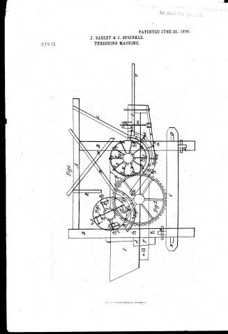
J. Barley and J. Sprinkle's Patent Drawing for a Thrashing Machine

National Archives, Restored Patent Drawings (Record Group 241) · Full-size scan at the National Archives · Catalog record
Show the text on the drawing Hide (47 words)
Words on the drawing as machine-read by the National Archives; not checked. Useful mainly for searching.
130. THRASHING. / Finter / Thrashing Machines. / A. Cylinder Machines. / 12 / #9741x / J B.ARLEY and J SPRIYKLE / THRASHING MACHINE / CLASSIFICATION / 9741x / Patented 20th June 1836. / DIVISION. / Frig 6. / Figt / in / on / my / is / 20 / Frg.s / [. / 72. / 300 / (b)
National Archives restored drawings: drawing
Henry Durell's Patent Drawing for a Comb

National Archives, Restored Patent Drawings (Record Group 241) · Full-size scan at the National Archives · Catalog record
Show the text on the drawing Hide (157 words)
Words on the drawing as machine-read by the National Archives; not checked. Useful mainly for searching.
us. / 132, / Combs. TOILET, HENRY & / #97412 / COMB. / CLASSIFICATION / Patented / 97411-1 / DIVISION. / H. / A. / I. / B. / G. / C. / d. / da / F. / e. / G. / H. / A. / A. / B. / e/c. / c. / c. / c. / e d. / d. / d. / d. / e e. / e. / e. / e. / H. / HEIVCHS . / A.A. 8gc. Plates of metal, with holes punched in them forming the teeth of the Comb. / B. B. . Short plates of metal, with holes in them; to be placed between the teeth, and / regulate their distance apart. / c,d, e. c,d,e. goc. The holes in the plates, through which the wires pass. / F. The large wire, or rod, pafsing through the middle of the Comb. / G.G. The smaller sized wires, for the other two holes. / H. H. The Combs, when put together / I. Shows the wires, ore rods; with some of the plates put on
USPTO scan
The patent as scanned by the USPTO
-
 Page 1
-
 Page 2
-
 Page 3
-
 Page 4
-
 Page 5


U.S. Patent and Trademark Office · Google Patents
Show the transcription Hide (2,023 words)
Machine transcription (LightOnOCR) of the pages as scanned by the USPTO, most of them the handwritten copies made when the records were restored after the 1836 fire. Not checked; it can misread handwriting, so compare it with the scan.
Page 1.
PATENTED JUNE 20, 1836.
J. BARLEY & J. SPRINKLE.
THRESHING MACHINE.
9741X

Page 2.
June 20, 1836
Jacob Bailey and John Sproule
Proctors Patents
The subject referred to in this specification: Patents and one thing part of the device containing a description in the terms of the said Jacob Bailey and John Sproule, the title of their improvement on the machine for threshing wheat and other seed.
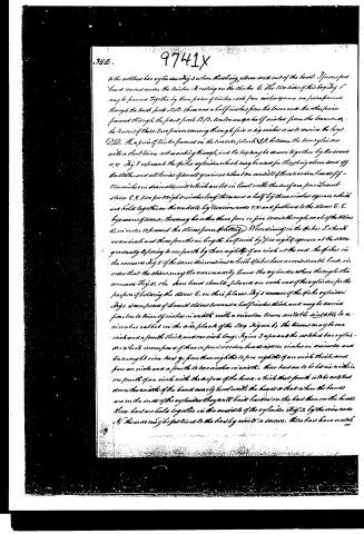
To all to whom these presents shall come, Be it known that we Jacob Bailey and John Sproule of the County of Rockingham and State of Virginia have invented a new and useful wheat and other seed threshing machine and that the following is a full and exact description thereof. The improved threshing machine for threshing all kinds of small grain as wheat, barley, and oats, and other seed, off the stalk and out of the head, consists of a threshing box, two open cylinders, two conical or egg-shaped and pointed or head-shaped and pointed. Figure 1 represents the threshing box consisting of four posts B, B, B, B, the two front posts each four feet eight inches in height and four inches square; the two back posts each four feet two inches in height also four inches square; two side planks A, A, each six feet two inches in length, three inches thick, thirteen inches in width, intersecting three inches of the ends of the notched bar cylinders Fig. 2 from the base to the end, they are reduced to five inches from the lower edge. These side planks A, A are rabbeted one inch where they come against the front posts B, B, the front posts may also be rabbeted one inch; the back posts are rabbeted one inch in front, they come against the planks A, A, then rabbets may also be cut large enough to receive the side planks A, A, and fastened to the posts B, B, by the screws C, C, the bars G, G are each four feet nine inches long, four by four inches square, three pieces G, G are framed into the front and back posts B, B, B, B, seven and a half inches from the lower end with a tenon passing through the posts seven or eight inches in order to receive the bars G, G. The left side is represented by the letter H, tenon into the front post B, B, with a mortise suitable to a tenon on the back post B, B, H, the rabbet for the front shackle bears to the spike cylinders Fig. 1, H, H, rabbets for the back shackle bears to the spike cylinders Fig. 1, and front shackle bears to the notched bar cylinders Fig. 2, the shackle bears H, may be used to the spike cylinders Fig. 1 when threshing grain, the other end off the stalk, or it may be used at the front shackle bears to the notched bar cylinders Fig. 2 when threshing other seed out of the head. H, back shackle bears
Page 3.
to the notched bar of the same Fig. 3 when the string above said out of the bowl. I have for found round under the timber A, resting on the timber C. The two sides of this box Fig 1 may be framed together by three pieces of timber each four inches square one piece framed through the back joints D,D. three and a half inches from the lower end, the other piece framed through the front joints B,B, three and a half inches from the lower end, the lower of these two pieces coming through five or six inches so as to receive the bars D,D. A piece of timber framed in the lower side plank A,B, between the two cylinders with a short lion not reaching through, and the box may be drawn together by the corners or, or Fig 1 resembles the spike cylinder which may be used for the string above said off the table and all kinds of small grains as wheat be consist of three or four lines of fifteen inches in diameter with which are let in level with the surface four board staves C,C, five feet eight to inches long, three and a half by three inches square which are held together in the middle by two iron wires r,r, and fastened to the staves E,E. by means of screws, there may be either three four or five screws through each of the staves C, in order to prevent the staves from splitting. When driving in the spikes I in the box are one inch and three fourths in length half inch by five eighths square at the stone gradually tapering to one fourth by three eighths if an inch at the end. the spikes in the cone are Fig 5 of the same dimensions as the spikes have a considerable bend, in order that the grain may the more easily leave the cylinder when through the cone as Fig 6. the base band should be placed on each end of the cylinder for the purpose of holding the staves C, in their places. Fig 3 is a view of the spike cylinder Fig 1, is composed of board staves three and a half inches thick and may be varied from two to twenty inches in width with a circular frame suitable suitable to a cylinder called in the side plank of the box Fig 6, the staves may be one inch and a fourth thick and one inch long. Fig 3 is a view of the notched bar cylinder which is composed of three or four wooden boards nine inches in diameter and two and a half iron bands y, from three eighths to five eighths of an inch thick and from an inch and a fourth to two inches in width, these bands are to be let in within one fourth of an inch with the surface of the head, so that that fourth is to be notched down the width of the band nearly level with the hoops so that where the bands are on the ends of the cylinder they will butt harder on the band than on the hoops. these bands are held together in the middle of the cylinder Fig 3, by the iron wires A, these wires may be fastened to the band by rivets or screws, these bands have notab
Page 4.
9741X
323.
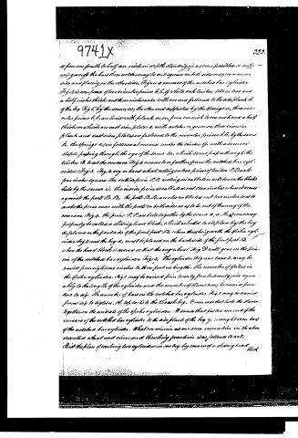
a from one fourth to half an inch in depth standing in a cross position or making across the bars these notches may be cut square on both sides or square on one side and sloping on the other side. Figure 4 represents of the notched bar cylinder Fig. 2 is a cross section of the circular pieces b, b, of white oak timber, two or three and a half inches thick and three inches wide with one end fastened to the side plank d. of the top Fig. 1, by the screws c, the other end supported by the springs e, the circular pieces b, b, are lined with plank w, w, from one inch to one inch and a half thick on which are cast iron plates a, with notches or grooves, these circular plank and cast iron plates are fastened to the circular pieces b, b, by the screws f, the springs e are fastened at one end under the timber g, with a screw or staple passing through the eye of the screw m, which screw passes through the timber d, to set the screws Fig. 3, square to or fasten from the notched bar cylinder Fig. 3. Fig. 2 a g or band wheel resting on two pieces of timber P, P, which from under square the outside piece P, P, resting in at the O or notches in the blocks held by the screws c, the inside piece is a flat bar and two inches when it comes against the posts B, B, the posts B, B, are also on the line out two inches so as to make the pieces even with the posts on both sides so as to be out of the way of the concave Fig. 4. The pieces P, P, are held together by the screws a, a, the pieces may properly be called a sliding head block, which as shown to be placed by the key a, placed on the front side of the front post B, when the spring with the spoke cylinder Fig. 1, and the key a, must be placed on the back side of the front post B, when the head block is moved so that the way shown Fig. 2 will gear on the section of the notched bar cylinder Fig. 3. The cylinder Fig. 1, may be varied from eighteen inches to three feet in length. The number of spokes in the spoke cylinder Fig. 1 may be varied from twenty four to twenty five agreeably to the length of the cylinder and the number of stones may be varied from two to six. The number of bars in the notched bar cylinder Fig. 3 may be varied from six to fifteen. H. left side to the head block, to join and that holds the stones together in the middle of the spoke cylinder. It seems that just on one end of the concave of the notched bar cylinder to the side plank of the top y, through one bar of the notched bar cylinder. What we conceive as our own invention in the above described wheel and drive and threshing machine was follows to art:
First the plan of working two cylinders in one key by means of a sliding head block.
Page 5.
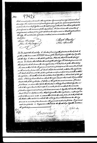
block so constructed as to work either on cylinders by means of one or any number of screws. The improvement of making an open cylinder by means of which it is turned about one half lighter and the dispensing with about two thirds of the spikes formerly used in the common spike machines. It also claims the invention of using conical instead of straight spikes as huts for use in threshing machines. Thirdly, The notched bar cylinder is claimed as an innovation in its own right.
Lucas H. Hartsy
John E. Hartsy
Jacob Barley
John Sprinkle
13, 13, posts to the threshing box. 6, timbers framing the front and back posts to gether at the lower ends. 20, 20, timbers of the timbers framing the box together also the hogs. 6, screws in the spike cylinders. 8, screws that hold the spring screws. 6, timbers that holds the ends of the springs. 16, timbers framed into the side planks between the two cylinders. 17, side planks of the threshing box. 18, screws that holds the groove cast iron plates and the circular planks on the circular pieces b, b, 14, back slats board to the notched bar cylinder. 11, back slats board to the spike cylinder and front slats board to the notched bar cylinder. 12, rods that holds the notched bar together in the middle of the cylinder. 13, sliding head block on which the conical band wheel rests. 15, front slats board to the spike cylinder. 16, spikes in the cylinders and conveyors. 17, screws front board. 18, screws that hold the timbers or sliding head block together on which the conical band wheel rests. 6, circular pieces on which the circular planks and groove cast iron plates are screwed. 4, hogs that holds the sliding head block to its place when threshing with either cylinders. 2, springs on which the conveyor rests. 6, screws that holds the side planks to the posts, also the blocks with a notched iron head the sliding head block moves on. 19, spring screws. 10, circular planks under the groove cast iron plates. 6, groove cast iron plates. 11, large screws that hold the threshing box together between the cylinders.
Published accounts: journal notice
Notice in the monthly list of patents
Journal of the Franklin Institute, new ser., vol. 18 (1836), p. 215 · View the page
443. Thrashing machine.-J. Bailey and J. Sprinkle, Rockingham, Va.
About this record
- Patentee
- DATAMP
- Date
- the Name and Date index of patents, DATAMP, USPTO records
- Invention
- DATAMP
- Listed in
- the Name and Date index of patents, DATAMP, USPTO records, Jim Shaw's X-patent list, the Journal of the Franklin Institute, Burke's List of Patents (1847)
- The Franklin Institute's journal spells the name differently.
- Burke's 1847 Patent Office list gives the same patent.
Shaw: lists Durell, H. here as 9741½