

Drawings and documents
National Archives restored drawings: drawing
Jesse C. Wood's Patent Drawing for a Machine for Raising Water

National Archives, Restored Patent Drawings (Record Group 241) · Full-size scan at the National Archives · Catalog record
Show the text on the drawing Hide (78 words)
Words on the drawing as machine-read by the National Archives; not checked. Useful mainly for searching.
108. PUMPS / Rotary. / 4 Singlo Piston. / f2. / Sesse C Heed / 1836 / 9763.1 / DIVISION. / Machine for Graining Water / Vol. 6. ps.30. / 9763 X / Riferenses. threathed apentures wingson Reservoir / a double screw. f the drum or cover. c. d paddles. e / of oonshot whul / Patent office has 10th 1841. / Anade under the direction of th Commitsioner of Patento / in conformity with act of 3.V march 1838 / Commisions of Ontent. / JA / inmo use
USPTO scan
The patent as scanned by the USPTO
-
 Page 1
-
 Page 2
-
 Page 3


U.S. Patent and Trademark Office · Google Patents
Show the transcription Hide (439 words)
Machine transcription (LightOnOCR) of the pages as scanned by the USPTO, most of them the handwritten copies made when the records were restored after the 1836 fire. Not checked; it can misread handwriting, so compare it with the scan.
Page 1.
9763X
J. C. WOOD.
MACHINE FOR RAISING WATER.
Patented June 22, 1836.

THE MORRIS PETERS CO., PHOTO-LITHO., WASHINGTON, D.C.
Page 2.
June 22, 1834
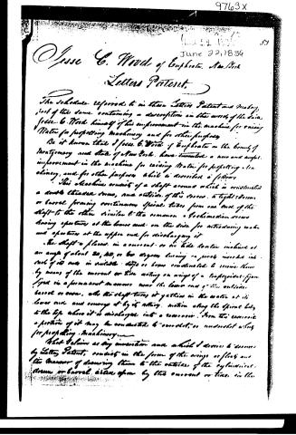
Jesse C. Wood of Euphemia, New York
Letters Patent.
The Schedule referred to in these Letters Patent and making part of the same containing a description in the words of the said Jesse C. Wood himself of his improvement in the machine for raising Water for propelling machinery and for other purposes.
Be it known that I Jesse C. Wood of Euphemia in the County of Montgomery and State of New York, have invented a new and useful improvement in the machine for raising Water for propelling machinery, and for other purposes which is described as follows:
This machine consists of a shaft around which is constructed a double threaded screw, and outside of this screw, a tight barrel or barrel forming continuous spiral tubes from one end of the shaft to the other similar to the common screw mechanism screw having apertures at the lower end and on the side for introducing water and apertures at the upper end for discharging it.
The shaft is placed in a current or in side water inclined at an angle of about 30, 40, or 60 degrees having a pivot inserted into each of its ends in suitable slots or boxes constructed to receive them by means of the current or tide acting on wings of a tripointed figure fixed in a permanent manner near the lower end of the outside barrel or screw, as the shaft turns it gathers in the water at its lower end and conveys it by its rotary motion along the spiral body to the top where it is discharged into a reservoir. From this reservoir a portion of it may be conducted to a wheel, or undershot wheel for propelling machinery.
That I claim as my invention and which I desire to secure by Letters Patent, consists in the form of the wings or floats and the manner of drawing them to the outside of the cylindrical screw or barrel driven upon by the current or tide in the
Page 3.
9763X
34
manner before described for turning the machine above mentioned for raising
beats to be applied to various purposes
Witness:
M. J. Slicht
Edward T. Bode
Drew to Work
396 no.
Drawing made.
Published accounts: journal notice
Notice in the monthly list of patents
Journal of the Franklin Institute, new ser., vol. 18 (1836), p. 287 · View the page
511. Crane. Gilbert Sherwood, Erie, Penn.
About this record
- Patentee
- DATAMP
- Date
- the Name and Date index of patents, DATAMP, USPTO records
- Invention
- DATAMP
- Listed in
- the Name and Date index of patents, DATAMP, USPTO records, Jim Shaw's X-patent list, the Journal of the Franklin Institute, Burke's List of Patents (1847)
- Burke's 1847 Patent Office list gives the same patent.