

Drawings and documents
National Archives restored drawings: drawing
William P. Brayton's Patent Drawing for a Machine for Spinning and Doubling Cotton

National Archives, Restored Patent Drawings (Record Group 241) · Full-size scan at the National Archives · Catalog record
Show the text on the drawing Hide (29 words)
Words on the drawing as machine-read by the National Archives; not checked. Useful mainly for searching.
11. / m 5 / SPINNIN / 1142 Throstles & Cape / lines / 25 18.36 / 9767-x / DIVISION. / 9767 / Drawing 2nd / Drawing / For / of
USPTO scan
The patent as scanned by the USPTO
-
 Page 1
-
 Page 2
-
 Page 3
-
 Page 4
-
 Page 5
-
 Page 6
-
 Page 7
-
 Page 8
-
 Page 9
-
 Page 10
-
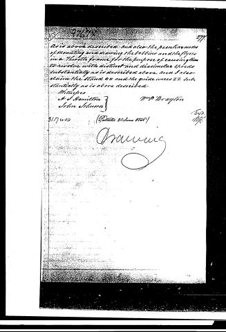 Page 11


U.S. Patent and Trademark Office · Google Patents
Show the transcription Hide (2,836 words)
Machine transcription (LightOnOCR) of the pages as scanned by the USPTO, most of them the handwritten copies made when the records were restored after the 1836 fire. Not checked; it can misread handwriting, so compare it with the scan.
Page 1.
No Printed Specification Available
9767X
W.P. Brayton,
Spinning Machine,
Drawing 1st Fig. 2
Patented June 25, 1836
Sheet 1 - 2 Sheets.
Page 2.
9767X
W. P. Brayton,
Spinning Machine,
Drawing 2nd Patented June 25, 1886
Sheet 2-2 Sheets.
Fig. 1
Fig. 2
Page 3.
June 25, 1836
William P. Brayton
New York
Letters Patent.
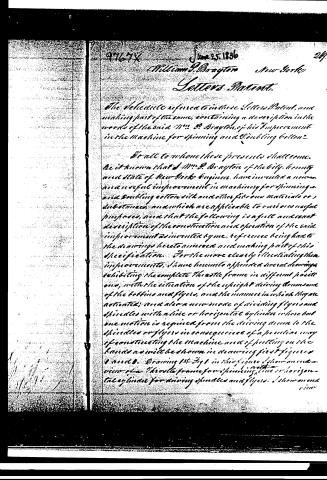
The specification referred to in these Letters Patent, and making part of the same, containing a description in the words of the said Wm. P. Brayton, of his "Improvement in the Machine for spinning and doubling cotton."
To all to whom these presents shall come.
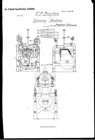
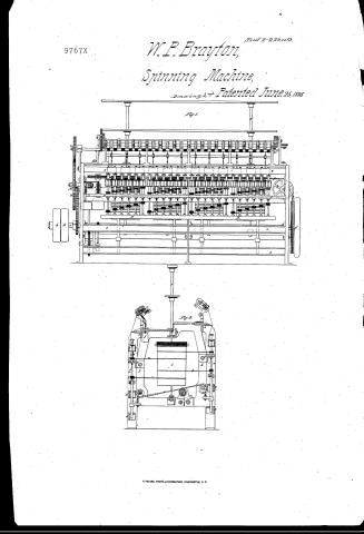
Be it known that I, Wm. P. Brayton of the city, county and state of New York, Engineer, have invented a new and useful improvement in machinery for spinning and doubling cotton, silk and other fibrous materials or substances, and which are applicable to various useful purposes, and that the following is a full and exact description of the construction and operation of the said improvement as invented by me, reference being had to the drawings hereto annexed and making part of this specification. For the more clearly illustrating the improvements, I have hereunto appended several drawings exhibiting the complete throstle frame in different positions, with the situation of the eight driving drums and of the bobbins and flyers, and the manner in which they are actuated; and also a new mode of driving flyers and spindles with a line or horizontal cylinder where but one motion is required from the driving drum to the spindles or flyers in consequence of a peculiar way of constructing the machine and of putting on the bands as will be shown in drawing first figures 1 and 2. Drawing 1st Fig 1 in this figure I show an end view of a throstle frame for spinning, with a horizontal cylinder for driving spindles and flyers. I show an end view
Page 4.
270 97677
view of the cylinders and view of the bands and also two spindles driven by the same which construction of spindles I claim as new and of my invention.
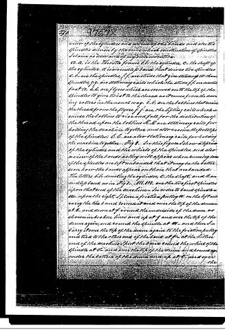
A. A. is the Throttle frame b. b. the cylinder, C. the shaft of the cylinder. d is an endless band that drives two spindles c. c. are the spindles, f. f. are studs that give standing to them spindles, g. g. are stationary rails which the studs f. f. are secured fast to, h. h. are flyers which are carried on to the top of the spindles to give twist to the thread as it comes from the drawing rollers in the usual way. l. l. are the bobbins that receive the thread from the flyers, j. j. are the lifting rails which cause the bobbins to rise and fall for the distribution of the thread upon the bobbins K. K. are stationary rails for holding the machine together and also receive the foot steps of the spindles. O. O. are also stationary rails for holding the machine together. Fig 3. In this figure I show a top view of the cylinder and the wheels of the spindles, and also a view of the bands as they will appear when running, some of the spindles are left unbraced that it may be the better seen how the bands appear on those that are braced.
The letters b. b. denoting the cylinder, C. the shaft, and d. an endless band as in Fig 1. M. M. are the two first spindles upon that end of the machine. In order to band spindles M. upon the right, I place a friction pulley W. on the left and carry the band from it round over the top of the drum at O. and down at f around the under side of the drum as shown in broken lines and up at g and over the top of the drum again, and round the spindle at M. and then I carry it over the top of the drum again to the friction pulley and tied to the other end of the band at f. at the latter end of the machine, but the band would the wheel of the spindle at M. and over the top of the drum and a round up under the bottom of the drum and up at O. and over the
Page 5.
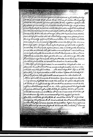
the top of of the drum again and around a friction pulley at 10 and back to 8 and tied. These friction Pulleys being placed the space of one spindle to the right or left for the purpose of binding the first or last spindle by. A 1/2 p distance would perhaps answer, and the spindles might be so placed in the machine as to need no friction pulleys but this I conceive to be the best way. It will be perceived that in binding spindles 8 & 10 that they may one space from being directly opposite to each other, this is to prevent the bands from running together over the top of the drum running off. A 1/2 space a full space of spindle might answer, but much depends on the width of the machine and the distance the spindles are set apart. variations enough should be made so that the bands will not run together over the top of the drum. In this way the whole frames may be made two feet wide and have cylinders in them fourteen or sixteen inches in diameter.
The top of the cylinder in a machine two feet wide as should be set about one and a half inches below the wheels on the spindles. In drawing 2nd figure 3 the spindle f is represented with a disc l upon it which fits fast before the spindle and carries the bobbin 3. This spindle is made to revolve by a band from the driving drum passed round the wheel 3. upon the spindle 4 tube 4 is affixed by its socket and screw nut to the upper stationary rail &c. the upper part being bushed to give steadiness with little friction to the spindle which revolves within it and is caused to slide up and down by the movement of the casting rail. In the outside of the tube 4 another tube 5 is fitted carrying the flyers 6, 6 and which last mentioned tube with the flyers are made to revolve by a band from the driving drum passed round the wheel 7 hence it
Page 6.
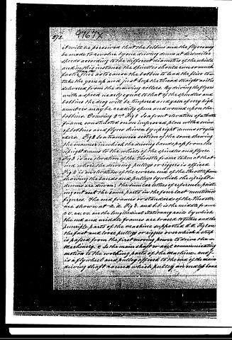
it will be perceived that the bobbins and the flyers may be made to revolve by one driving drum at dissimilar speeds according to the different diameters of the wheels and in this instance the spindles should run somewhat faster than the bobbins to cause the bobbin to lead the flyer to take the yarn up and just keep the thread straight as it is delivered from the drawing rollers. By driving the flyer with a speed nearly equal to that of the spindles and bobbin the drag will be tempered and yarn of very high numbers may be readily spun and wound upon the bobbins. Drawing 9 is a front elevation of that frame constructed on an improved plan with a series of bobbins and flyers driven by upright drums or cylinders. Fig 3 is a transverse section of the same showing the manner in which the driving bands pass from the upright drums to the sides of the spindles and flyers. Fig 3 is an elevation of the throttle frame taken at M and m, where the driving pulleys or riggers is affixed. Fig 4 is an elevation of the reverse end of the throttle frame showing the bands and pulleys by which the upright drums are driven; the similar letters of reference pointing out the same parts in the four last mentioned figures. The end frames or standards of the throttle are shown at a, a. Fig 3, and b, b. is the middle frame c, c, e, e, are the longitudinal stationary rails by which the end and middle frames are braced together and the knuckle parts of the machine supported. d, d. Fig 4 are the fast and loose pulleys or riggers over which a strap is passed from the first moving power to drive the machinery. e is the main shaft or axle communicating motion to the working parts of the machine, and f is a flywheel and pulley affixed to the end of the main driving shaft round which pulley an endless band
Page 7.
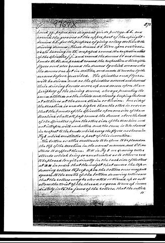
bands gg-passed over diagonal guide pulleys-h-h-and round the grooves at the upper part of the upright drum bb-for the purpose of giving rotary motion to the driving drums. These drums bb turn upon cast-iron axles bearing in tt. are passed round the respective whorls of the spindles j j, and round the drums cc and similar bands ll-ll are passed round the respective whorls of the flyers and also round the drums by which means when the drums are set in motion, and made to revolve by the means before described. The spindles and flyers will be driven and as the spindles ascend and descend their driving bands move up and down upon the periphery of the driving drums, always presenting the same attitude to the whorls and thereby keeping the bands at all times at the same tension or tension. One side of the machine is made higher than the other in order that the bands of the spindles upon one side of the machine shall all pass round the drums above the bands of the spindles upon the other side of the machine and not interfere with each other and the same is to be observed in respect to the bands which carry the flyers as shown in Fig 2 which constitutes a part of this invention.
The bottom or other materials to be spun to be placed on the top of the machine in the usual manner, and v-lime stands to support them. N.N. in Fig 9 are drawing rollers stands which being so constructed as to allow a rod to be placed longitudinally in the back side of the stand at xx in order that the weight that causes the top drawing rollers to press upon the bottom ones may put pressure to the extent of the bottom drawing rollers and that the rollers may be elevated or turned up so as to allow the twist of the thread or yarn to run up immediately into the jaws of the rollers, that the article
Page 8.
to be spun may receive the twist as soon as the drawing rollers leave it, which is found to be extremely necessary when spindles are run at very high speed and more particularly in the spinning of fine yarns. The wire that is attached to the weight y Fig 8 and the wire in which is lifted on a longitudinal rail, or drop rails maybe substituted and supported at each end by the bottom longitudinal stationary rails and in this case the drums may be driven by infinite or bevil wheels, for which in slow motions for spinning rovings in the back or bottom Fig framed for which this principle of driving is also claimed Bevil gearing would perhaps be most suitable, and the spindles or shafts of the drums are confined in rollers, in a longitudinal rail at the top as shown in Fig 8. The spindles f.f. are arranged in series on each side of the frame supported in steps at the bottom by the capping rails k.k. and passed through tubes and sockets in the upper stationary longitudinal rail c.c. The bobbin being upon a disc mounted upon the upper part of the spindles and turning therewith. The flyers are attached to a tube as before described with a wheel affixed to the flyer tube the capping rails k.k. supporting the spindles are made to twist fast for the purpose of winding the yarn in uniform coils on upon the bobbins by the ordinary contrivances, that is to say by connecting these rails to pendant chains b.b. attached to longitudinal shafts m.m. which reach the whole length of the Machine. Another chain H. Fig 8 is attached to a pulley O on shaft M and made fast at the lower end to the lever p, which lever is mounted on a stud set in a transverse carrier rail, q and is made to vibrate by the rotation of the bevil wheel r, a loose and balance weight being attached to the lower end of the lever. These two lifting rods m.m. Fig 8 are connected by
Page 9.
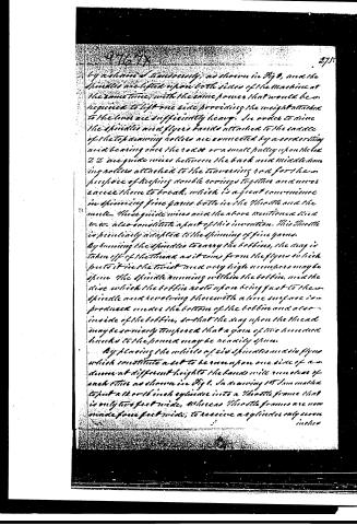
by a common treadle, as shown in Fig 9, and the Spindles are lifted upon both sides of the Machine at the same time, with the same power that would be required to lift one side providing the weight attached to the lines are sufficiently heavy. In order to raise the Spindles and flyers bands attached to the saddle of the top running rollers are connected by a cord or string and bearing over the rods or a small pulley upon the rod 2 2 2 are guide wires between the back and middle running rollers attached to the traversing rod for the purpose of keeping double rows together and never cause them to break, which is a great convenience in spinning fine yarns both in the Shuttle and the mule. These guide wires and the above mentioned kind W-W also constitute a part of this invention. This Shuttle is peculiarly adapted to the spinning of fine yarns. By running the Spindles to empty the bobbins, the yarn is taken off of the thread as it comes from the flyer which puts it in the finest and very high numbers may be spun. The Spindle running within the bobbin, and the disc which the bobbin rests upon being fast to the Spindle and revolving thereon with a line surface is produced under the bottom of the bobbin and also inside of the bobbin, so that the yarn upon the thread may be so nicely tempered that a yarn of two hundred hanks to the pound may be readily spun.
By placing the wheels of six Spindles and six flyers which constitute a set to be run upon one side of a drum at different heights the bands will run clear of each other as shown in Fig 1. In drawing 1st I am made to put a 16 or 18 inch cylinder into a Shuttle frame that is only two feet wide, whereas Shuttle frames are now made four feet wide, to receive a cylinder only seven inches
Page 10.
inches in diameter, which cylinder must sometimes as fast as mine to give the same speed to the spindles and at the same time is not able to stand as high speed as a larger cylinder, and by having a small cylinder, the whirls on the spindles are often made small in order to get the necessary speed, which is very distinctive to the spindles by being obliged to have the bands much tighter, by having a large cylinder, I am enabled to have the whirls on the spindles larger and consequently am able to run spindles with a slackened band, and again by putting the band all around the cylinder, it gives the cylinder more power upon the band and the band will be able to be slackened so that no sound and the slackened band is run the better it will last, and the longer the spindles will last, and again the bands in this way have straight upon one side of the whirls of the spindles and upon the other side, have an angle of only one inch and a half to the foot.
What I claim as my invention is the method of banding and driving the spindles substantially as is described in the above specification and referred to in drawing 1st Fig 1st & thereby saving one half of the room in the width of the Throttle frame, and being enabled to use a large cylinder instead of a small one which is in all cases desirable; I also claim the spindle substantially as described above and referred to in Fig 1st drawing 1st. I also claim the peculiar construction of the parts of a Throttle frame for spinning and for doubling substantially as is described above and referred to in drawing 8th.
I also claim the adaptation of upright arms or cylinders for driving the spindles and the flywheel by distinct bands in a Throttle frame substantially as
Page 11.
As is above described and also the peculiar modes of mounting and driving the bobbin and the flyer in a shuttle frame for the purpose of causing them to revolve with distinct and dissimilar speeds substantially as is described above, and I also claim the stand 44 and the guide wires 22 substantially as is above described.
Witnesses:
A. J. Hamilton
John Johnson
Wm. P. Brayton
31.7.1865
(Patented 25 June 1866)
[Signature]
Published accounts: journal notice
Notice in the monthly list of patents
Journal of the Franklin Institute, new ser., vol. 18 (1836), p. 287 · View the page
460. Cotton, spinning. William P. Brayton, N. Y.
About this record
- Patentee
- DATAMP
- Date
- the Name and Date index of patents, DATAMP, USPTO records
- Invention
- DATAMP
- Listed in
- the Name and Date index of patents, DATAMP, USPTO records, Jim Shaw's X-patent list, the Journal of the Franklin Institute, Burke's List of Patents (1847)
- Burke's 1847 Patent Office list gives the same patent.