

Drawings and documents
National Archives restored drawings: drawing
S. Whitman's Patent Drawing for a Rotary Steam Engine

National Archives, Restored Patent Drawings (Record Group 241) · Full-size scan at the National Archives · Catalog record
Show the text on the drawing Hide (104 words)
Words on the drawing as machine-read by the National Archives; not checked. Useful mainly for searching.
121 STEAM ENGIRES, / Rotary Impact. / tool 25. nage 389- / #1- / paterled 25"Lune1836 / 9784.X / Rotary Steam engine / DIVISION / 9784X / Ilan / Patented June 25-1836. / A Cast Iron Wheel with Rim ot Flarge / B. Trangular leellz / C. Circular plate or wheel find attached A / D. central slationary male secused to Box d / by dasteungs. / I Conductor 07 conveyor of Strame / Sections / G. Shaft / H. Pulley / ON / AF / in / Stricklands Det / Patent office Seption 1843 / Made under the direction of the commissioner / of Patents in conformity with ach of 3 March / 1837 / Mr Elemonth / Commissioner of Patels
USPTO scan
The patent as scanned by the USPTO
-
 Page 1
-
 Page 2
-
 Page 3
-
 Page 4
-
 Page 5


U.S. Patent and Trademark Office · Google Patents
Show the transcription Hide (1,319 words)
Machine transcription (LightOnOCR) of the pages as scanned by the USPTO, most of them the handwritten copies made when the records were restored after the 1836 fire. Not checked; it can misread handwriting, so compare it with the scan.
Page 1.
9784X
S. WHITMAN.
ROTARY STEAM ENGINE.
Patented June 25, 1836.

Page 2.
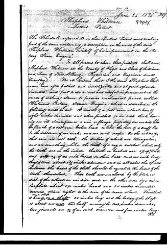
The Schedule referred to in these Letters Patent and making part of the same containing a description in the words of the said Shepherd Whitman himself of his improvement in the Rotary Steam Engine.
To all persons to whom these presents shall come, Shepherd Whitman in the County of Floyd and State of Indiana and Town of New Albany, Physician and Engineer sends Greeting.
Be it known that I the said Shepherd Whitman have after patient and investigation and at great expense invented and put to use a new and useful improvement in the mode of working steam to produce mechanical power, called Whitman's Rotary Steam Engine, which is described in the following words to wit: It consists of a cast iron wheel twenty eight inches diameter and when finished ½ an inch thick having on its circumference a row of flanges projecting one and a half inches like the flanks of a cast iron boiler head or like the corn of a snuff box to the distance of one inch and one inch deep. On the inside of this rim are cast teeth, the section of which are triangular and are something like the teeth of a cog or calotte wheel, only the teeth are on the inside. These teeth or knuckles are 5/8 of an inch deep and 1/4 of an inch broad on their base and one inch long. They stand about 1 1/2 inches apart and in all cases the spaces between the bases of the teeth should be equal to the bases of the teeth themselves. These teeth are enclosed by the plate or disk of the wheel on one side, and on the other side by a circular plate about 5 1/2 inches broad and 2 1/2 inches diameter screwed steam tight to the rim of the main wheel. This wheel is hung on a shaft 30 inches long and the body of the shaft is about one and one half or may be two inches diameter. Two journals are 1/4 of an inch diameter and five inches long.
Page 3.
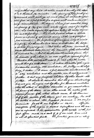
This shaft may be made of steel or iron but steel is the best. The journals run on leather, but for larger ones good bell metal is thought to be preferable. There is a central stationary wheel secured in its proper place by fastenings to the cast iron box which envelopes the whole. This central stationary wheel is of such diameter that when placed between the sides of the main wheel and the flat cone or ring that the bottom of the groove which is made around the whole circumference of this stationary wheel, which is one inch wide, 3/8 of an inch deep, will approach the inner points of the buckets to the distance of 3/8 of an inch. This central stationary wheel has attached to it at the open side a conductor or conveyor of the steam which directs the steam to the face of the teeth or buckets directing the steam in a line as near at right angles with the radius of the wheel as may be. The mouth of the conductor stands in the groove of the stationary central wheel, the open of which at the discharging point is one inch long 3/16 wide. The case which envelopes the engine may be made square or round as best suits the fancy of the builder, but if made square room may be left at the bottom to heat the supply water. The steam escapes immediately behind the conductor by an opening made for this purpose through the centre stationary wheel and is discharged on to the case or envelope through a circular opening around the other shaft. And there is the gun air through an opening of proper size at any convenient place. On the shaft towards one end is placed a cast iron or other metal pulley 5 inches diameter and 6 inches long. This pulley carries a leather belt over the surface of a wheel some 5 or 6 feet diameter thus receiving the motion until it drives the furnace fan. The motion of this engine will be where the steam is at one hundred pounds to the superficial square inch about six thousand revolutions per minute when at work but when running
Page 4.
moving without any load its motion would be something like at least 10 or 11 thousand per minute. The opening of the depth of a square inch will discharge as much steam at 100 pounds of pressure as 15 feet of boiler fire surface will make under ordinary circumstances. The engine I have just described having an opening of 1/64 of an inch would require 12 x 15 fire surface, 180, and would require two cylinders boilers 20 inches diameter and 26 feet long. This would produce about a 30 horse power or a power of 460 pounds moving at the rate of 1080 feet per minute. The proportions of this engine may be varied to infinity, but the one here laid down is at this time the best for a 30 horse power engine. But when the power amounts to 100 or thousand horse power the diameter of the wheel should be increased &c. But it is the universal opinion that the diameter of the wheel in no case ought to exceed five feet. Bands or belts are in all cases to be used when the motion exceeds that of a mill stone. To reduce the motion of the engine here described making 1080 revolutions the pulley on the shaft being 5 inches. A drum 6 feet diameter would reduce it to 416 1/2 revolutions and this motion can be easily reduced further to suit any purpose whatever by other bands and pulleys. It should be remarked that the gear should always be so as to give the engine not less than five thousand revolutions when the actual is 28 inches diameter or you cannot obtain the power of the steam or in other words the motion of the circumference of the wheel should never be less than one half of the motion of the steam you are working. See with the motion is about 1800 hundred per second or 108,000 feet per minute for at the one half that or 54,000. A further description of the engine is deemed superfluous and the reader is referred to an examination of the model at the patent office made on a scale of 1/4 of an inch to an inch in all its essential parts. The peculiar ground on which
Page 5.
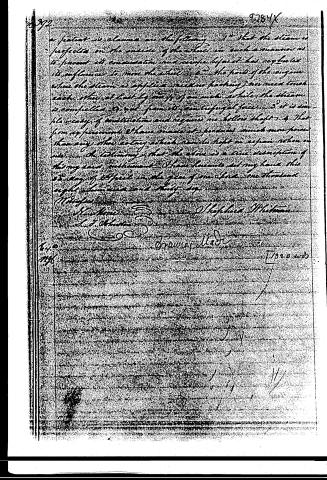
a patent in claims are the following: 1st That the steam is projected on the outside of the wheel in such a manner as to prevent its condensation and except before it has neglected its influence to move the wheel. 2d The parts of the engine where the steam is applied need no packing; nor need touch each other at least by way of an inch while the steam is confined to act from its centrifugal force. 3d It is simple ready of construction and requires no hollow shaft. 4th That from experiments I have made it produces much more power than any other engine which can be kept in repair when in use. In testimony that the above is a true description of this my said instrument I have hereunto set my hand this 23 day of April in the year of our Lord one thousand eight hundred and thirty.
[Signature]
Stephen Whitman
A. J. Whitman
Drawn & Made by [Signature]
[1830 wds]
Published accounts: journal notice
Notice in the monthly list of patents
Journal of the Franklin Institute, new ser., vol. 18 (1836), p. 287 · View the page
477. Rotary steam engine. Shepherd Whitman, New Albany, Ind.
About this record
- Patentee
- DATAMP
- Date
- DATAMP
- Invention
- DATAMP
- Listed in
- the Name and Date index of patents, DATAMP, USPTO records, Jim Shaw's X-patent list, the Journal of the Franklin Institute, Burke's List of Patents (1847)
- The sources give different dates; the date shown is the one most of them agree on.
- The Franklin Institute's journal confirms the date shown.
- Burke's 1847 Patent Office list gives the same patent.
- Burke's 1847 Patent Office list gives a slightly different date; the date shown follows the standard lists.