

Drawings and documents
National Archives restored drawings: drawing
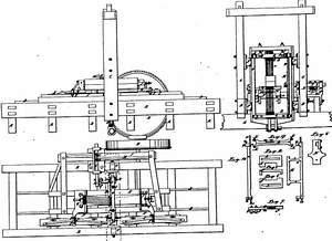
Charles M. Keller's Patent Drawing for a Machine for Sawing Bilged Staves

National Archives, Restored Patent Drawings (Record Group 241) · Full-size scan at the National Archives · Catalog record
Show the text on the drawing Hide (50 words)
Words on the drawing as machine-read by the National Archives; not checked. Useful mainly for searching.
143. WOOD SAWING. / Banels Wood / Reciprocating Saw Mills. / #350 / Charley H. challen's / DIVISION / 97984 / 9798X / Muchine for Suncing / it / in2819757 / Mts / Gr / the / Fig. g / Fíg 8 / The / 000000 Q / Fig 4 / L. / Fig. 10 / 1, / Fig.7 / -g. / not / not
USPTO scan
The patent as scanned by the USPTO
-
 Page 1
-
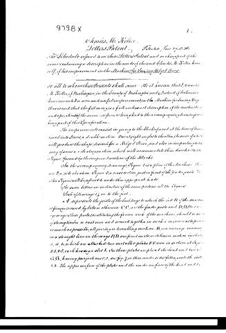 Page 2
-
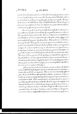 Page 3
-
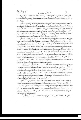 Page 4
-
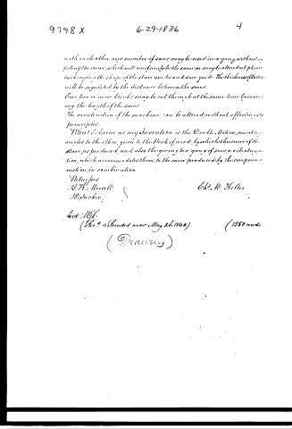 Page 5


U.S. Patent and Trademark Office · Google Patents
Show the transcription Hide (1,558 words)
Machine transcription (LightOnOCR) of the pages as scanned by the USPTO, most of them the handwritten copies made when the records were restored after the 1836 fire. Not checked; it can misread handwriting, so compare it with the scan.
Page 1.
X0009798
C. M. Keller,
Making Stares.
Patented June 29, 1886.
A.M. PHOTO-LITHO. CO. N.Y. (PROPRIETOR)
Page 2.
9798 X
1.
Charles W. Kellee
Letters Patent. Patented June 29, 1856.
The Schedule referred to in these Letters Patent and making part of the same, containing a description in the words of the said Charles W. Kellee himself, of his improvement in the Machine for Slicing Bicycles.
To all to whom these Presents shall come: We it known, that I, Charles W. Kellee, of Washington, in the County of Washington and District of Columbia, have invented a new and useful improvement in the Machine for Slicing Bicycles, and that the following is a full and exact description of the construction and operation of the same: reference being had to the accompanying drawings, making part of this Specification.
The improvements consist in giving to the block referred to at the time of being turned into slices, a double motion. One at right angles to the other, the same motion will produce the shape desired for a Bicycle Slice, and also in imparting to the gang of saws a vertical motion, which will accommodate their direction to the figure formed by the compound motion of the Blocks.
In the accompanying drawings, Figure 1 is a plan of the Machine. Figure 2, a side elevation. Figure 3, a cross section, just in front of the feeder posts. The other Figures will be referred to under their appropriate heads.
(The same letters are indicative of the same parts in all the Figures)
Scale of Drawings: 1/2 in to the foot.
A represents the joists of the building, to which the ends B of the machine are firmly secured, by bolts or otherwise. C, C, are the feeder posts, and D, D, the carriage ways. These parts, constituting the frame work of the machine, should be made of strong timber or cast iron and secured together in such a manner as to prevent as much as possible, all jarring or trembling motion. B, is a carriage running in a straight line on the ways D, D, confined in its rectilinear motion by blocks a, a, to which are attached two metallic plates B', B', seen in section at Figures 4, 5, 6, 7, each having a slot b. On these plates are placed the head and tail c, c, having projections c', c', engaging in their under sides fitting into the slots b, b. The upper surface of the plates and the under surface of the head and tail
Page 3.
blocks should be planished and the slots b, b, and projections c, c, should be made to fit snugly so as to cause the head and tail blocks to slide easily and without warbling at right angles to the carriage B. The depth of the head and tail blocks, and by which the blocks or blocks designed to serve are made fast, are seen at c, c, f, and may be altered at pleasure as the mode of fastening is not material.
The carriage B, may be moved back and forth in the same manner as the carriage of a saw mill, viz. by a wag wheel, pinion, and rack. The arrangement is represented at H. There is a slot in one end of the head and tail blocks, in which are fixed the spindles of two rollers g, g, with set-screws and nuts for the purpose of setting them. These rollers are each side of the slave guides J, J. These guides are made of iron, and bolted to each side of the saw bed, which is let into the bed of the machine, and regulated by wedges. To each end of the carriage is attached an arm of wood or iron extending beyond the guide posts to which the saw guide bar T, is bolted. The guide K is either cast with the bars, or attached to it so as to run with it firmly. The shape of the saw guide will always be governed by the slave guides, and length of the lever (to be hereafter described) which gives motion to the saw. The slide L, is provided with two sets of rollers h, h, at one end, playing on each side of the saw guide, and two others i, i, playing on each side of the bar M. This slide moves in an iron frame N, see fig. 8.
The saw guide O, which is made of cast iron, and works in blocks P, P, P, P, which are bolted to the fence posts is put in motion by a pitman which connects the machine with the moving power. There are two cross heads Q, Q, affixed to the guide. The metal at the bottom is firmly bolted in its place, and turns at top so as to slide up or down, and regulated by the screws j, j, and is provided at each end with set screws k, k. These cross heads are made in two pieces, as seen at a, and kept together by the screw bolts l, l. Six holes, very accurately bored in the cross heads, and in which the saw hangs its work, are seen at m, m. In these holes, the saws n, n, are attached, see fig. 10. The hanging in the cross heads have heads turned on them, as at o, and thereon the upper head screws cut in the iron ends furnished with nuts and washers, (see p. fig. 10) are
Page 4.
small feather which prevents the vibratory motion of the hangers from affecting the screws. The hangers y, y, have round pins working into holes made in two connecting bars R, R.
On one side of the saw gate is a tumbling shaft S, with two pins at each end working in holes made in the cross heads, on a line with the holes in which the hangers work. There are two arms S S, extending from the tumbling shaft, to the end of which is attached the round bar of iron N, which plays between the rollers i, i, before described. Near each extremity of the tumbling shaft is a lever t, t, with a pin working into a hole in the ends of the connecting bars.
The screws N, N, are connected with the hangers by pins, as seen at N, N, fig. 10.
OPERATION. (The blocks of wood being cut to the length required for slaws, and with sufficient to prevent the saw from cutting out at the sides, and with their mass a little more than the width of a slaw, are inaccurately placed in the head and tail blocks and secured in their place by the dogs. The saw gate is then set in motion, and, when in readiness, the block is impelled against the saw by the motion of the carriage, which is in a direct line towards them. The head and tail blocks, however, are movable in the slots, which are at right angles with the motion of the carriage, and are governed in this, their lateral motion, in position by the shape of the curve of the slaw guides.
As the first rollers in the head and tail blocks act on each side of the slaw guides, it is evident that as the carriage advances these blocks, together with the bar which is changing its character, into slaws, has a motion at right angles to the motion of the carriage, the sum of which two motions describes a curve similar to that of the slaw guides, and that the saw, by cutting this curve, has a curve in the blocks of wood in the form of slaws.
The change of direction or vibration of the saw which accommodates them to the above described curves is obtained by means of the saw guide K, which being firmly connected with, and moved by the carriage K, gives motion to the bar N, on the tumbling shaft, by means of the slide I, which motion causes the saw to vibrate or change the direction in which they cut according to the shape of the guide K.
As the curve given to the slaws is produced by two motions at right angles,
Page 5.
with each other, any number of saws may be used in a gang without affecting the curve, which will uniformly be the same, or may be altered at pleasure by changing the shape of the slown guides and saw guides. The thickness of the saws will be regulated by the distance between the saws.
One, two or more blocks may be cut through at the same time by increasing the length of the saws.
The construction of the machine can be altered without affecting its principles.
What I claim as my invention is the Double Motion, one at right angles to the other, given to the block of wood, by which the curves of the slown are produced, and also the giving to a gang of saws a vibratory motion, which accommodates them to the curves produced by the compound motion in combination.
Witnesses
B. H. Morrell
J. R. Tucker
Cht. M. Keller
Date: May 6
(No. 4 & Recorded anew May 26, 1840.) (1550 words)
(Drawing)
Published accounts: journal notice
Notice in the monthly list of patents
Journal of the Franklin Institute, new ser., vol. 18 (1836), p. 287 · View the page
510. Sawing staves. Chas. M. Keller, Washington, D. C.
DATAMP: illustration
Illustrations from DATAMP

DATAMP (Directory of American Tool and Machinery Patents), via the Internet Archive · Archived DATAMP page
About this record
- Patentee
- DATAMP
- Date
- the Name and Date index of patents, DATAMP, USPTO records
- Invention
- DATAMP
- Listed in
- the Name and Date index of patents, DATAMP, USPTO records, Jim Shaw's X-patent list, the Journal of the Franklin Institute, Burke's List of Patents (1847)
- The Franklin Institute's journal spells the name differently.
- Burke's 1847 Patent Office list gives the same patent.
- Burke's 1847 Patent Office list gives a slightly different date; the date shown follows the standard lists.