

Drawings and documents
National Archives restored drawings: drawing
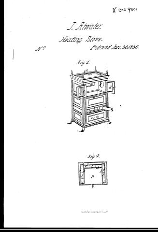
James Atwater's Patent Drawing for a Stove

National Archives, Restored Patent Drawings (Record Group 241) · Full-size scan at the National Archives · Catalog record
Show the text on the drawing Hide (45 words)
Words on the drawing as machine-read by the National Archives; not checked. Useful mainly for searching.
126. - roves& NACES / [154] Heating Stoves. / // / JAMES A TWATER'S / classiFication / 9801X / in III OD V / DIVISION. / Patented 30"line th 1836 / Figure 1. / n. / nt / thrish / finst / ojamas. / Figuro 2. / bl3.
USPTO scan
The patent as scanned by the USPTO
-
 Page 1
-
 Page 2
-
 Page 3
-
 Page 4
-
 Page 5
-
 Page 6


U.S. Patent and Trademark Office · Google Patents
Show the transcription Hide (1,973 words)
Machine transcription (LightOnOCR) of the pages as scanned by the USPTO, most of them the handwritten copies made when the records were restored after the 1836 fire. Not checked; it can misread handwriting, so compare it with the scan.
Page 1.
X 0009801
J. Atwater.
Heating Stove.
No. Patented Jun. 30, 1836.
Fig. 1.
Fig. 2.
A. P. L. & Co., Photo-Lithographers, Washington, D.C.
Page 2.
6/30/1836 9801 X
av. 14
June 30, 1836 521.
James Atwater.
Letters Patent
The schedule referred to in these Letters Patent and on the first part of the same containing a description in the words of the said James Atwater himself of his improvement in stoves for burning Anthracite Coal.
To all people to whom these presents shall come. We know ye that James Atwater of the town of New Haven in the County of New Haven and State of Connecticut, a citizen of said State and of the United States, have invented a new and useful improvement in Stoves used for burning hard or Anthracite coal and that the following is a description of the construction and operation of my improved stove and of my invention. This stove is in the form of a rectangular Prism, and may be about fifteen inches wide and thirteen inches deep and twenty eight inches high, or in any other suitable proportions. For ornament it may have projecting at the top and bottom, forming mouldings and giving the appearance of a basement capital. It is supported in the usual way by four feet at the four corners. The front plate has three openings one near the base for an ash draw, one a little higher, for a small door below the fuel to admit air and to aid the draft and for other purposes and one near the top for a large or double door above the fuel through which the stove is fed. Each door has a single lap on it to show the fire and the interior of the stove. The rear plate has one opening near the top to which a pipe may be attached to conduct off the smoke gases from the fire. The extreme side plates are without openings. The top and bottom plates with their openings hereafter described and with their mouldings or projections complete the outside of the stove and at that has the appearance of an ordinary rectangular cast iron stove. Its peculiarities consist principally in the interior arrangement which are as follows: Within the side and rear plates already described are three inside plates (viz) one on each side and one in the rear and these plates are placed about five eighths of an inch from the outside plates and about one inch and one quarter
Page 3.
6/30/1836 9801 X
522.
ten of an inch from the outer rear plate. Each of these middle plates has an opening near the top through which drafts or flues are to be made to pass and the middle rear plate has an opening below the grate or fire for the same purpose. Each of these middle plates at the sides has projections or flanges perpendicular to their interior surface on the whole length of the sides and extending from the sides about one third of the way across the bottom and that portion of the plate between the two points where the flanges terminate on the bottom is extended downward about four inches which extension has the same flange on each side to its termination which the whole plate has already described. Both of these middle side plates are alike. The middle rear plate has flanges across the bottom, and it is formed at the bottom with an extension in the middle and flanges in the same manner as the middle side plates are formed. The flanges project about two inches. Within the plates last described are three additional and innermost plates of the same length as the last three and placed so as to come in close contact with all the flanges in the middle plates. The two innermost side plates extend from the front to the rear plate and all three of the innermost plates have the same projecting part from the middle of the bottom downward which the middle plates have so that when the two sets of plates (viz) the middle and innermost plates are carefully placed together they form three rectangular tubes at the bottom of each pair about four inches in length. Each of the innermost plates has the same openings that the middle plates have. The bottom plate has three openings of a size and shape and position to correspond with the three rectangular tubes already described and these openings must be carefully fitted to receive the tubes. The top plate has open work over the space or chamber between the two sets of interior plates. Each of the openings in the two sets of interior plates are connected by a tube or flue making a communication and communication from the inner chamber through the middle chamber to the outer chamber and through these flues the several draughts of the fire are formed. There are small projections cast at the bottom and on the inside of the three innermost plates, on which a movable plate rests and forms a chamber between this and the bottom plate. On the inside of the innermost rear plate below the grate or fire a slide or stopper is placed in the usual way which opens and
Page 4.
and closes the flue which passes through the middle chamber into the rear chamber below the grate or fire. This forms the lower or downward draught. On the outside of the opening at the top of the middle rear plate is placed a slide or stop, furnished with a handle projecting upward through the top plate by which the flue above the fire which passes through the middle chamber into the rear chamber is opened and shut. This forms the upper direct draught. Inside of the innermost plate is a lining of fire brick or other suitable substance in the usual manner and a grate on which the fuel is placed. One of the bars of the grate near the middle of the same, has a hollow groove on the under side which rests on a rod which draws out in front and then the grooved bar and one or two others with which it is connected turn on a hinge or pivot, and drop down and empty the contents of the stove which rest on the grate with the ash pan below. The moveable part of the grate is then brought back and made to rest on the rod which is replaced as before. The top plate has a rectangular opening of the size of the part of the stove which contains the fuel and over this opening is placed a moveable plate which can be removed at pleasure. That this description may be more easily understood I add a drawing containing two figures. Figure I. shows a perspective view of an improved stove. a, denotes the ash door in the opening made therefor. b, shows the opening for the small door below the grate. The large opening for the double door a, a, is shown immediately above. Figure II. shows a horizontal section of the stove above or below the fire brick and the observer is supposed to look downward upon the same. f, f, f, show the movable plates on the sides and rear. Figure I g, g, shows one of the openings opening through one of the side plates and the opening through the rear plate through which openings the upper draughts of the stove are formed. Figure II i, i, i, shows side flanges on the movable plates at the sides. k, k, k, show the innermost side and rear plates. The openings through the bottom plate are denoted at C, C, C. Figure III m, m, m, shows the open work in the top plate. The handle of the stopper which opens the opening through the upper part of the middle rear plate is seen at n. Figure II o, shows a small projection attached to a movable plate which is immediately
Page 5.
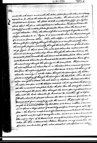
under the ash drawer and with the bottom plate forms the chamber already described. Fig. 3 shows the chamber of combustion. The spaces above the bottom plate and between the plates b, b, b, and the plate f, f, f, of a light in shade show the pure atmospheric air chambers. The spaces between the plate f, f, f, and the outside plate of a darker shade show the burnt air and gas chamber. When the stove is filled and ready to be ignited and the stopper attached to it, Fig. 4 is removed the stove has the direct draught of a common furnace stove. When this stopper is closed and prevents the draught from passing through the stopper and near flue directly, then the draught passes indirectly through the side flues one of which is seen at g, Fig. 5, thence down the outer side chamber called above the burnt air and gas chamber, thence through the chamber between the movable plate beneath the ash drawer and the bottom plate, thence up the outer back side chamber for burnt air &c as above described thence off in the usual way through the opening in the rear plate. The furnace air in the atmospheric air chamber, is in the meantime warmed by radiation from the adjoining plate and is thus made to circulate through its chamber coming in at the bottom through the openings in the bottom plate and passing off through the openings in the top plate. When the direct stopper draught is closed, the ash drawer in its place, the lower door shut, the upper door open and the stopper removed which regulates the opening in the innermost iron plate below the fire then the draught is drawn upward through the fuel, then through the lower opening of the air and then into the back chamber for burnt air &c and then off as before. (This flue should be opened whenever the stove is cleaned of ashes, &c to prevent dust from ascending into the room.) The principle object sought to be accomplished by this stove is to secure within a common space a large extent of radiating surface so arranged as to diffuse the heat on a rapid and effective manner while all the benefits of a direct and powerful draught when needed are retained and also (the advantage of a downward draught to prevent scattering dust when the stove is cleaned up.) I claim therefore as my invention the peculiar combination of the above described atmospheric air chamber
Page 6.
6/30/1836 9801X
(560) 525
but with the indirect draught and one or both of the other draughts which combination is so modified as to cause the heat when the indirect or circular draught is used to come in contact with all the outer plates of the stove, and also at the same time with all the middle plates and flanges which form part of the said stove plates and chambers while the innermost plates which complete the same are when hot are heated by the direct action of the fire in the ordinary manner.
And I do not claim the whole stove as new nor any of the several separate parts thereof nor any other combination than that above described nor the construction of the whole or any part thereof except so far as is required to accomplish the modified combination claimed as aforesaid.
In testimony that the foregoing is a true specification of my said improvement I have hereunto set my hand at New Haven this sixth day of May 1836 one thousand eight hundred and thirty six
Witness
Samuel A. Whitehead
Philly R. Sanford
James H. Water
2016 mt
Ex. 4
cl. 1
Published accounts: journal notice
Notice in the monthly list of patents
Journal of the Franklin Institute, new ser., vol. 18 (1836), p. 287 · View the page
501. Stoves. James Atwater, New Haven, Conn.
About this record
- Patentee
- Jim Shaw's X-patent list
- Date
- the Name and Date index of patents, USPTO records, Jim Shaw's X-patent list
- Invention
- the Name and Date index of patents
- Listed in
- the Name and Date index of patents, USPTO records, Jim Shaw's X-patent list, the Journal of the Franklin Institute, Burke's List of Patents (1847)
- Burke's 1847 Patent Office list gives the same patent.