

Drawings and documents
National Archives restored drawings: drawing
Gilbert Sherwood's Patent Drawing for a Crane

National Archives, Restored Patent Drawings (Record Group 241) · Full-size scan at the National Archives · Catalog record
Show the text on the drawing Hide (18 words)
Words on the drawing as machine-read by the National Archives; not checked. Useful mainly for searching.
16 / 2x / 8, / oil
USPTO scan
The patent as scanned by the USPTO
-
 Page 1
-
 Page 2
-
 Page 3
-
 Page 4


U.S. Patent and Trademark Office · Google Patents
Show the transcription Hide (788 words)
Machine transcription (LightOnOCR) of the pages as scanned by the USPTO, most of them the handwritten copies made when the records were restored after the 1836 fire. Not checked; it can misread handwriting, so compare it with the scan.
Page 1.
9813X
G. Sherwood,
Derrick.
Patented June 30, 1836.

A.M. PHOTO-LITHO. CO. N.Y. (OSBORNE'S PROCESS)
Page 2.
June 30, 1836
Gilbert Sherwood of Erie, State of Pennsylvania
Letters Patent.
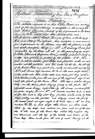
The schedule annexed to this Letters Patent and making part of the same containing a description in the words of the said Gilbert Sherwood, himself of his improvement in the Crane.
To all to whom these presents shall come,
Be it known that I Gilbert Sherwood of Erie in the County of Erie and State of Pennsylvania, have invented a new and useful improvement in the Crane and that the following is a full and exact description thereof;
1st. A stationary Crane post designated by the letters A. B. in the accompanying draft (entitled "Sherwood Improved Crane") resting perpendicularly on a step and secured in position by the fastener E. F. This post is about eighteen feet long and fourteen inches in diameter at the fastener and ten inches at the top. On the top of the Crane Post is a pivot five inches in diameter and six feet long marked B. B. in the said draft twelve inches wide and three inches deep and nine feet long with a hole twelve inches from the one end of the sufficient size to admit the pivot of the Crane Post. The cap is placed horizontally on the Crane post playing freely on the pivot. The opposite end being supported by the braces marked D. D. in said draft.
2nd. A saddle marked C. C. in said draft this and a half feet long fourteen inches wide by twelve deep resting on the fastener and playing round the foot of the crane post at right-angles to the crane cap.
3rd. Two braces marked D. D. in said draft these braces are three inches thick by six deep and extend one from each end of the saddle to the end of the Crane Cap which they support. They are tenoned into the top of the saddle and bottom of the Crane Cap three inches from the end of each leaving at the
Page 3.
point of the Crane Cap three inches between the braces.
D, F, a windlass marked C, in the same draft three feet long and nine inches in diameter, affixed to the top of the brace two feet from their junction with the saddle by caps marked F. In said draft, three caps are about six feet long and of the same thickness with the braces, to which they are fastened by bolts. The Paterson G, D, are sixteen inches wide by twelve inches deep and should be riveted with iron bolts to prevent splitting. Near the end of the Crane Cap, exactly between the ends of the braces is a hook for the purpose of fastening a tackle. H, this hook is secured by an iron plate on the top of the Crane Cap and is of sufficient strength to support several tons weight.
I, J, and K, are hooks marked in said draft with the letter I, this is made of a bar of iron one inch square, with a hook one foot long and shank three feet long with a bolt attached to the handle. The improved Crane is designed to be used on board of steamers in raising stone and any other heavy body from the water and in raising and lowering timber and stone in building of wharfs, etc. The feature and principle by which it may be distinguished from other Cranes is the saddle and two braces, by means of which any amount of power may be applied to move the body suspended from the Crane, horizontally without danger of diminishing the strength of the crane or endangering its breaking. In use the body should be erected in the centre of the scene, and in addition to the paterson the crane post is further supported by stay chains. In raising weights with the crane a tackle is attached to the hook on the crane cap with the fall fastened to the windlass and when the body is raised sufficiently, it is moved horizontally to the place desired on the scene, when the stone to be raised is set close to the ground the stone hook is placed under one side of it after which the
Page 4.
9813X 1/
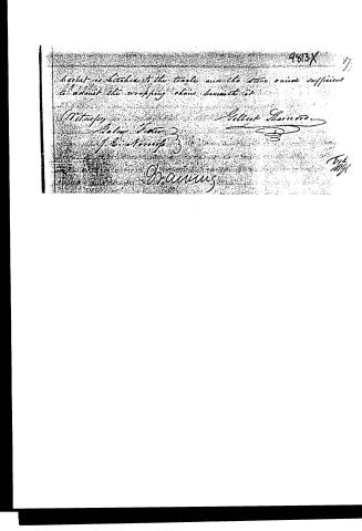
hermit is hitched to the trachea and the stone raised sufficient to admit the wrapping chain beneath it
Witness
Albert Sharnood
J. C. Atteridge
Dramus
Feb 11/41
About this record
- Patentee
- DATAMP
- Date
- the Name and Date index of patents, DATAMP, USPTO records
- Invention
- DATAMP
- Listed in
- the Name and Date index of patents, DATAMP, USPTO records, Jim Shaw's X-patent list, Burke's List of Patents (1847)
- Burke's 1847 Patent Office list gives the same patent.