

Drawings and documents
National Archives restored drawings: drawing
David Hess' Patent Drawing for a Manner of Raising Water

National Archives, Restored Patent Drawings (Record Group 241) · Full-size scan at the National Archives · Catalog record
Show the text on the drawing Hide (35 words)
Words on the drawing as machine-read by the National Archives; not checked. Useful mainly for searching.
03. PUMPS. / [118] Windlasswaterelevators. / #1 / DAVID HESS9 / DIVI TON / 9830 + / Manner ofraising water / 9830 X / Patented July 1st 1836 / Iig,2. / Ko / TOTAL / of / M. / OL
USPTO scan
The patent as scanned by the USPTO
-
 Page 1
-
 Page 2
-
 Page 3
-
 Page 4


U.S. Patent and Trademark Office · Google Patents
Show the transcription Hide (979 words)
Machine transcription (LightOnOCR) of the pages as scanned by the USPTO, most of them the handwritten copies made when the records were restored after the 1836 fire. Not checked; it can misread handwriting, so compare it with the scan.
Page 1.
9830X
D. Hess,
Windlass Water Elevator,
Patented July 1, 1836.
Fig. 2

Fig. 1

M. PETERS, PHOTO-LITHOGRAPHER, WASHINGTON, D. C.
Page 2.
9830x
July 1, 1836
David Hess of Shepherdstown (Virginia)
Letters Patent.
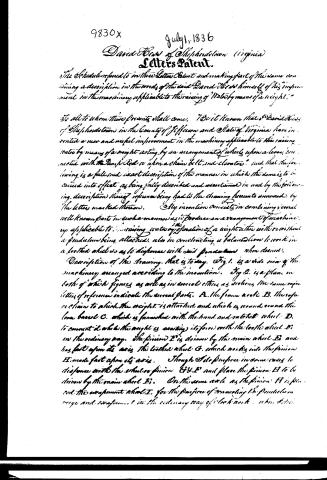
The Schedule referred to in these Letters Patent and making part of the same containing a description in the words of the said David Hess himself of his improvement in the machinery applicable to the raising of Water by means of a weight."
To all to whom these presents shall come. To it known that I David Hess of Shepherdstown in the County of Jefferson and State of Virginia have invented a new and useful improvement in the machinery applicable to the raising water by means of a weight acting by an arrangement of wheels upon a lever, connected with the Pump Rod or upon a chain belt, and elevator, and that the following is a full and exact description of the manner in which the same is to be carried into effect as being fully described and ascertained in and by the following description thereof reference being had to the drawing hereunto annexed, by the letters marked thereon. My invention consists in combining several well known parts in such a manner as to produce an arrangement of machinery applicable to the raising water by operation of a weight either with or without a pendulum being attached, also in constructing a balanced lever to work in a locked wheel as to dispense with said pendulum when desired.
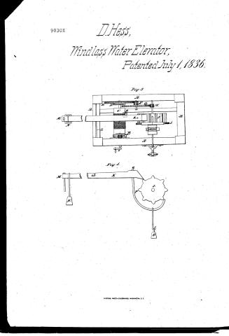
Description of the drawing. That is to say. Fig 1. is a side view of the machinery arranged according to the invention. Fig 2. is a plan in both of which figures as well as in several others as sections the same reference letters of reference indicate the several parts. A. the frame axle B. the rope or chain to which the weight is attached and which is wound round the lower barrel C. which is furnished with the hand and ratchet wheel D. to connect it while the weight is exerting its force with the toothed wheel E. in the ordinary way. The pinion F is driven by the main wheel B and has fast upon its axis the toothed wheel G. which works into the pinion H. made fast upon its axis. Though I do propose in some cases to dispense with the wheel or pinion G & F and place the pinion H to be driven by the main wheel B. On the same axle as the pinion H is placed the escapement wheel I. for the purpose of connecting the pendulum verge and escapement in the ordinary way of clock work when desired.
Page 3.
9830X
July 1, 1836
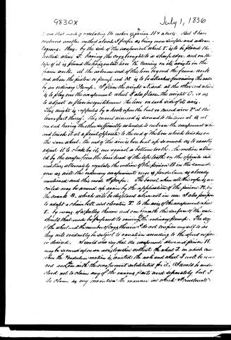
to use that mode of regulating the motion of pinion H & wheels. But I have conceived another method which I prefer as being more simple and advantageous. Thus, by the side of the escapement wheel T, is to be placed the toothed wheel J, having the cogs brought to a sharp edge, and on the top of it is placed the horizontal lever K, turning on its axis in the frame work. At the extreme end of this lever beyond the frame work and where the piston or pump rod M is to be attached, forming the water by an ordinary pump. I place the weight A and at the other end which is to play over the escapement wheel I also place the weight O, so as to adjust or place in equilibrium the lever on each side of its axis. This weight is supported by a hook upon the bent or curved wire P at the lower part thereof. This curved wire rod is secured to the lever at Q at one end, having the other sufficiently extended to embrace the escapement wheel and touch it at a point opposite to the end of the lever which touches on the same wheel. The end of the wire is here bent up so much as to exactly adjust it to shake by its use against a bottom tooth. The motion allowed by the escape from the lower head of the top tooth on the opposite side and thus alternately regulates the motion of the pinion H in the same degree as with the ordinary escapement verge & pendulum as already mentioned and this mode I prefer. The barrel when all the rope is uncoiled may be wound up again by the application of the pinion R, by the crank S, which will be displaced when not in use. I also propose to adapt a chain belt and elevator T, to the axis of the escapement wheel T, by means of a pulley thereon and one beneath the surface of the water should that mode be preferred to raising the ordinary pump. The size of the wheel and the number of cogs thereon I do not confine myself to as they will evidently be subject to variation according to the speed or power desired. I would also say that the escapement wheel and pinion H may be secured upon an axis together without the wheel J, in which case when the pendulum motion is wanted the axle and wheel J will be removed and one with the escapement substituted for it. I would be understood not to claim any of the various parts used separately but I do claim as my invention the manner in which I constructed
Page 4.
9830x
July 1, 1836
adopt the above K. motion which is to act to regulate the motion of the pinion H.
Witnesses:
Henry Stone
B. H. Morrell
David H. C. et al.
924 words) (drawing)
About this record
- Patentee
- DATAMP
- Date
- the Name and Date index of patents, DATAMP, USPTO records
- Invention
- DATAMP
- Listed in
- the Name and Date index of patents, DATAMP, USPTO records, Jim Shaw's X-patent list, Burke's List of Patents (1847)
- Burke's 1847 Patent Office list gives the same patent.