

Drawings and documents
National Archives restored drawings: drawing
Michael Freytag's Patent Drawing for an Ice Breaker


National Archives, Restored Patent Drawings (Record Group 241) · Full-size scan at the National Archives · Catalog record
Show the text on the drawing Hide (94 words)
Words on the drawing as machine-read by the National Archives; not checked. Useful mainly for searching.
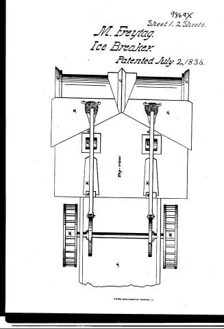
Sheet 1. $4- / D. BOATS. / L137] Ice Boats & Breakers. / CLASSLACATION / 9869-4 / DI VISION / Michael strugges / 9869 X / In Breaker / Patented 2 July 1836. / Lo / Side view. / Patent office 29th Sept 1808 / Reference A a boat / Made under the direction of the Commiproma / B the boat. / C Quard. / D Apton. / E Hammer / of fatents in conformity with act March 1837 / F. fulerum / G guides. / H theslide / I friction zoller. / K cam / L Spring / Hemyn Elmooth / .M. the Wheel. / Commissioner of Patents.
Sheet 2. O/R,
USPTO scan
The patent as scanned by the USPTO
-
 Page 1
-
 Page 2
-
 Page 3
-
 Page 4


U.S. Patent and Trademark Office · Google Patents
Show the transcription Hide (717 words)
Machine transcription (LightOnOCR) of the pages as scanned by the USPTO, most of them the handwritten copies made when the records were restored after the 1836 fire. Not checked; it can misread handwriting, so compare it with the scan.
Page 1.
9869X
Sheet 1. 2 Sheets.
M. Freytag.
Ice Breaker.
Patented July 2, 1836.
Top-view.
M. PETERS, PHOTO-LITHOGRAPHER, WASHINGTON, D.C.
Page 2.
No Printed Specification Available
9869X
Sheet 2. 2 Sheets.
M. Freytag.
Ice Breaker.
Patented July 2, 1836.
Side view.
Page 3.
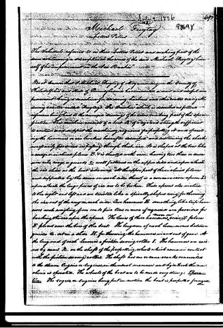
July 2, 1836
Michael Freytag
Letters Patent
The Schenectady referred to in these Letters Patent and making part of the same containing a description in the words of the said Michael Freytag himself of his improvement on the "Ice Breaker".
It is to be known that Michael Freytag of the County of Philadelphia and State of Pennsylvania has invented a new and useful improvement being a machine for breaking icebergs and other boats navigating during winter called Freytag's "Ice Breaker" which is described as follows reference being had to the annexed drawings of the same making part of this specification. The machine consists of a boat A of a size and strength sufficient to contain and support the machinery required for propelling it and operating the hammers or ice breakers hereafter described and sustaining the shocks necessarily produced in operating through thick ice. It is shaped at the bow like a canoe or inclined plane B. It is sheathed with iron, having two or more iron rails, ways, or guides C well fastened on the upper side and upon which the ice slides as the boat advances. All the upper part of this inclined plane and supported by the same on each side thereof is a concave iron apron D, upon which the large pieces of ice are to be broken. These aprons also incline to the right and left and are twisted like a specially shaped wing for throwing the ice out of the way on each side. Two hammers E, something like trip hammers and weighing from one to five tons or more of weight are provided for breaking the ice upon the apron. The levers of these hammers pivot at fulcrum F, placed near the bow of the boat. The long arm of each lever moves between guides G, set in a slide H, for throwing the hammers in and out of gear. At the long end of each lever is a friction saving roller I. The hammers are raised by means K, on the shaft of the propelling wheel which comes in contact with the friction saving rollers. The shaft has one or more axles connected to the steam engine or engines in the usual manner and by which the machine is operated. The wheels of the boat are to be made very strong. Specimen. The engine or engines being put in motion the boat is propelled forward.
Page 4.
2474
R869X
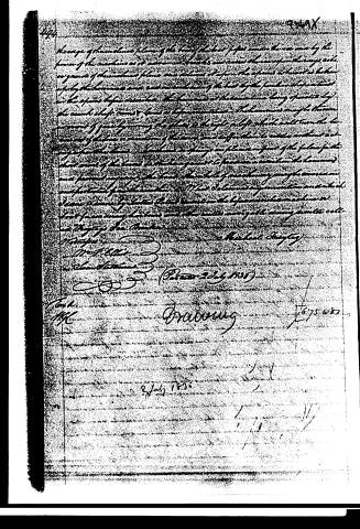
Hoavage of the machine plane of the head of the bed paper under the one end by the power of the machine as it advances the bed and raises the same for the way, etc. or gears of the machine plane and returns it upon the return of the bed is taken up by the hammer and acts on the bed by the punch in the position in the space before described. The hammer at the same time being operated by the crank shaft turns or moves a lever or motion. The hammer may be thrown forward or rear by moving the shaft to the right or left which will turn the lever and act on the motion of the same and suffer them to rotate without acting upon the hammer. A lever or spring on the end of the plane for the short end of the lever is attached to the hammer to produce a motion the hammer and prevent any injury to the bed. The whole of machinery may be covered and protected from the weather.
What I claim as my invention and which I desire to secure by Letters Patent is:—
1. The combination of the machine or bed for an ironing bed, and other parts arranged thereon, as described, etc.
Witness my hand this 2nd day of July 1835.
Michael Steytay
M. P. Ellis
J. S. M. Steytay
Patented 2 July 1835
T. H. C.
Drawing
2 July 1835
1675482
About this record
- Patentee
- Jim Shaw's X-patent list
- Date
- the Name and Date index of patents, USPTO records, Jim Shaw's X-patent list
- Invention
- the Name and Date index of patents
- Listed in
- the Name and Date index of patents, USPTO records, Jim Shaw's X-patent list, Burke's List of Patents (1847)
- Burke's 1847 Patent Office list gives the same patent.