

Drawings and documents
National Archives restored drawings: drawing
Chester Granger's Patent Drawing for a Cooking Stove

National Archives, Restored Patent Drawings (Record Group 241) · Full-size scan at the National Archives · Catalog record
Show the text on the drawing Hide (74 words)
Words on the drawing as machine-read by the National Archives; not checked. Useful mainly for searching.
126. STOVES & FURNACE / Cooking Stoves. / 12 / 9875 X / CHESTER GRANCER'S / looking Store / Patented 2nd July 18.86 / 9875=X / DIVISION. / as / It / Referees / A hallow cost iron box / B centre pun of iron box / C fure chamber / D ash put / E sven / F smoke flue / G stationary circular plate / H evreular plate or cap / I boiler holes / K roms avound boiler hotes
USPTO scan
The patent as scanned by the USPTO
-
 Page 1
-
 Page 2
-
 Page 3
-
 Page 4
-
 Page 5


U.S. Patent and Trademark Office · Google Patents
Show the transcription Hide (1,259 words)
Machine transcription (LightOnOCR) of the pages as scanned by the USPTO, most of them the handwritten copies made when the records were restored after the 1836 fire. Not checked; it can misread handwriting, so compare it with the scan.
Page 1.
9875X
C. Granger,
Cook Stove.
Patented July 2, 1886

Page 2.
July 2, 1836
Chester Granger 520 9875X
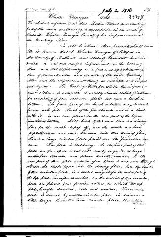
The structure referred to in the Spelter Patent and making part of the same containing a description in the words of the said Chester Granger himself of his improvement in the Cooking Stone.
To all to whom these presents shall come, be it known that I Chester Granger of Pittsford in the County of Rutland and State of Vermont have invented a new and useful improvement in the Cooking Stone and that the following is a full and exact description of the construction and operation of the said Cooking Stone and the improvement thereof, as invented and improved by me. The Cooking Stone for which the improvement relates is a stove, is usually made with a fire chamber consisting of four cast iron plates set upon a hearth or bottom. The front part of the hearth or bottom may be such for an ash pit. Back of the fire chamber and on a level with it, is an oven placed on the rear part of the before mentioned bottom. Still back of this oven there is a chiming flue for the smoke to pass off, and the smoke and heat pass both under and over the oven, into this chiming flue. There is a large circular plate placed over the fire oven or oven. The plate is stationary. So the front part of this plate an open space is cut out nearly or quite as large as the fire chamber, and placed directly over it. So the rear part of this plate another open space is cut out through which the smoke passes into the chiming flue. Into the center of this circular plate, is a socket designed for the rotation of the top plate hereafter described; on the outside of this circular plate are placed four friction rollers, on which the top plate, hereafter described, rests and revolves. This circular plate is covered by another circular plate in diameter a little larger than the lower circular plate, this upper circular
Page 3.
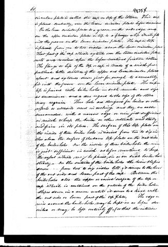
circular plate is called the cap or top of the stove. This cap is placed centrally, over the lower circular plate before described. On the lower circular plate is a groove on the outside edge, and on the upper circular plate or top is a flange or lip which fits into the groove on the lower circular plate. The cap or top is placed from one to two inches above the lower circular plate. That part of the cap which extends over the lower circular plate rests unsupported upon the before-mentioned friction rollers. The flange or lip of the top or cap is made of a width proportioned to the distance of the upper and lower circular plates apart and extends down just far enough to accurately fit into the groove on the lower circular plate. The cap or top is pierced with boiler holes in such number and size as convenience and a due regard to the size of the stove may require. These holes are designed for boilers or other pipes to be inserted in working, and they are cast or surrounded with a narrow edge or rim just sufficient in width to keep the boilers or other materials used steady and firm in its place. The surface of this top plate on the inside of these boiler holes is raised from two to six inches above the surface of the stove top plate on the outside of the boiler holes. On the inside of these boiler holes the rim is just sufficient in width as before mentioned to keep the surface which rests on the plates in or on such boiler hole steady. On the outside of the boiler holes the rim slopes down from two to six inches till it comes to the level of the outside and lower part of the cap. Between the boiler holes also the upper or raised surface of the top or cap which is contained on the outside of the boiler holes slopes down in a curve until it comes to a level with the outside or lower part of the top plate. The edge or rim around the boiler holes may be kept on as before described or may be left entirely off (so that the interior
Page 4.
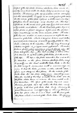
surface of the top plate between the boiler holes would be exactly on a level with the boiler holes) as convenience may dictate. The drawing of the top and slots which accompany this description is referred to as making a part of the same. On the inside of this plate is placed a hollow cast iron box of the form here to accompany every smoker etc. This box is fastened to the under side of the top by a bolt and screw or by rivets and cleats. On the lower side of this box is a central piece or joint designed to fit into the socket before mentioned, in the lower circular plate. The sides of this box are marked in such a manner as to fit the dimensions of the boiler which is designed to come next to them and each side is curved so as to be exactly fitted to the boiler intended to be inserted. This box may be made of whatever weight is judged most expedient. The central piece or joint above mentioned may be placed upon the lower side of this box. This last method is taken when it is desired to extend either of the boilers past the circle of the top. The upper top plate covers this box and as before described on the space between the boiler holes, may be exactly on a level with the boiler holes or the boiler holes may be surrounded with a narrow edge or rim, to keep the boiler guides or other utensils used, from and staying in their place. On the outside of the boiler holes the top plate slopes down something more than the width of this box and the boiler holes also the top plate slopes down in a curve the same width as before mentioned. The object of this central box is to raise the inner part of the top or cup within the boiler holes, nearly or quite to the level of the boiler holes thereby obviating the great inconvenience and difficulty in cleaning that part of the top plate when it is on a level with the part of the top plate which is outside of the boiler holes. The object in
Page 5.
tended to effect by the life assuming from the lower part of the centerboy, is that thereby, by altering the form and dimensions of the centerboy a larger boiler may be inserted by tending beyond the center of the life. The improvement of this boy and life may be used in other ways, as well as in one of the forms above described. The improvement of which I claim the invention and for which I ask letters patent of the United States consists in the centerboy used with or without the life as before described.
In witness whereof I have hereunto set my hand 20th day of May 1836
M. B.
Patentee
Wm. H. Kelley
Witness
Charles Granger
Witness
Patented July 2, 1836.
Drawings
About this record
- Patentee
- Jim Shaw's X-patent list
- Date
- the Name and Date index of patents, USPTO records, Jim Shaw's X-patent list
- Invention
- the Name and Date index of patents
- Listed in
- the Name and Date index of patents, USPTO records, Jim Shaw's X-patent list, Burke's List of Patents (1847)
- Burke's 1847 Patent Office list gives the same patent.