

Drawings and documents
National Archives restored drawings: drawing
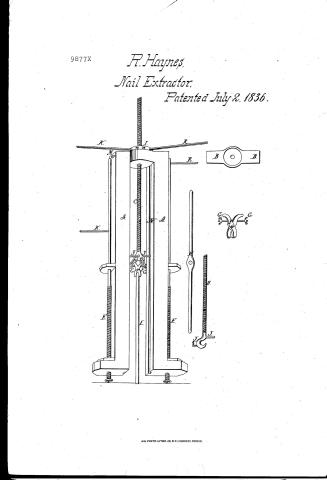
R. Hayne's Patent Drawing for a Method of Drawing Bolts of Spikes

National Archives, Restored Patent Drawings (Record Group 241) · Full-size scan at the National Archives · Catalog record
Show the text on the drawing Hide (21 words)
Words on the drawing as machine-read by the National Archives; not checked. Useful mainly for searching.
Signature facks / bl / eags / by
USPTO scan
The patent as scanned by the USPTO
-
 Page 1
-
 Page 2
-
 Page 3
-
 Page 4


U.S. Patent and Trademark Office · Google Patents
Show the transcription Hide (1,433 words)
Machine transcription (LightOnOCR) of the pages as scanned by the USPTO, most of them the handwritten copies made when the records were restored after the 1836 fire. Not checked; it can misread handwriting, so compare it with the scan.
Page 1.
9877X
R. Haynes,
Nail Extractor,
Patented July 2, 1836.
![Diagram of a Nail Extractor with labeled parts: A, B, C, E, G, I, J, K, L, M, N, R. The main body is labeled A, with internal components including a screw mechanism and levers. Part B is a circular component with a central hole. Part G is a pair of pliers. Part J is a hook-like component. Part K is a horizontal bar. Part L is a vertical rod. Part M is a vertical rod with a screw. Part N is a vertical rod with a screw. Part R is a horizontal bar with a screw. The diagram also includes a side view and a top view of the device.]
A.M. PHOTO-LITHO. CO. N.Y. (OSBORNE'S PROCESS)
Page 2.
July 2, 1836
Richard Haynes
Letters Patent
The declarants express to us these Letters Patent and making part of the same containing a description in the words of the said Richard Haynes himself of his improvement in the machine for Drawing Bolts or Spikes.
It all to whom these presents shall come. Be it known that I Richard Haynes of the Town of Portsmouth in the County of Norfolk and State of Virginia have invented a new and useful machine for Drawing Bolt Spikes and that the following is a full and exact description of the construction and operation of the said machine as mounted by me. The machine should be constructed of enough iron—the principle parts of the frame formed by bending the bars in the middle at right angles, making two parallel legs fixed at the bottom. This upright frame has attached to it two drawing screws with three nut heads and two heads, at the top so long as without drawing bolt nuts and two stays for the head of the frame. The frame—the pair of parallel legs fixed at the bottom and connected at the top at right angles (the top being the middle part of the bars since which forms the whole frame). The top of the frame is enlarged and provided for the way of fingers of the Drawing screws which enlargement is only formed to receive the nut head of the drawing screws—the bottom is within the back screw central. Diagonally on the upper and outside, back (front leg) may be formed or attached in which to bolt the stays when necessary. From the center on the outside on the outside of each leg is projecting out at right angles with the top of the screw and frame to be provided for the passage of the side screws. The bottom of each leg is turned out at right angles corresponding with the axis of the said and provided with a screw hole for the lower part of the side screw to work in. Each leg is provided at entire length from the bottom to the top on the inside for the projections on the drawing screws to slide into. The stays may be simply one broken at one end and provided at the other. The side screws. The two bolts of right lengths in proportion to the frame their lower holes are screw and to fit the holes in the bottom of each leg. Their lower extremities in fact are formed like a large circular bolt head, on the outside of each is a pointed spur. Their upper holes are placed over the edge of the frame smaller than their lower holes.
Page 3.
on the plain part near the minute they are perpendicular for the reception of a line bar, when necessary. They are inserted below and just above through the feet and rest along side the frame to set or bring them the same. If the base is level and the frame of sufficient length, these screws may be used in one way. The Drawing screw, also of two kinds. The first is a bolt of sufficient length to enter with a thread its extent. The lower extremity is formed with two eyes in each of which hangs a single link, above and near the eyes and at right angles with them are projections sufficiently long to enter and slide in the side grooves of the frame where the screw is in its place through the top. This screw is for drawing plane belts, splices, &c. The second is similar to the first, except that instead of eyes and links at its lower extremity, it is three hook formed, and the projections to slide in the side grooves are placed in the direction of the hooks. This screw is for drawing (ring or eye belts. The projections on these belts made to fit in the side grooves are necessary to keep the belts horizontal while operating and thereby secure at from any unequal strains. The nut heads, also of two kinds. The first is a nut of the proper size to fit the Drawing screws, and made with dimensions of sufficient length to give the required force. This nut when adjusted will fit into the cup on the top of the frame. The second is a nut made only to fit either drawing screw and the cup on top of the frame, but instead of arms it is perpendicular like the barrel head of a crank or anstine for the reception of force hand. This nut is to be used when the situation of the object to be drawn (see includes the application of the first as in a screw, near the side, floor, &c. The force screw (or a Strong instrument shaped something like a Blacksmith's tongs. The jaws are concave within to receive the head of the belt or splice &c. The lips are slightly hollow and screw out to grip firmly the belt or splice &c. The upper ends of the shanks are trunnion and to pass through, at a convenient distance below these hooks, the shanks are not the gear and friction in the direction of their drawing for the reception of the drawing belt. The closing bolt, also of a perpendicular size to the tongs and of sufficient length to a minimum as can apply by a hook to turn the tongs on the head of the belt, splice, &c. and thereby exert a grip (provided it be otherwise suitable to a projecting or enlarged head.) The closing bolt has a nut on each end to screw up on the tongs to close them. Application of the object to be drawn is to draw or in a line with the surface of work to be drawn.
Page 4.
98777
231.
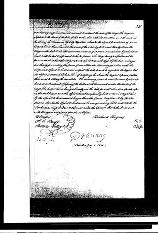
is on a way sufficient turned around to admit the use of the tongue. The tongue are applied to the head of the belt. Make V in a line with its direction and the ends on the closing belt screwed tightly together. Should the object be a titanic of an unusual length then handle the arms of the closing belt and thereby turn the tongue on the belt V in the same manner as if it was a screw plate by which a head will be not sufficient to hold firmly. The tongue being adjusted at the frame or as it so that the tongue extends up between its legs. If the head is irregular thereby preventing the frame from otherwise standing in a line with the tongue and object to be drawn adjust the side screws to regulate the legs so that the object is accomplished. Then if necessary hook in the tongue at top and fasten them so as to steady the machine. The drawing screw is next lowered by the nut head so as to admit of placing the links at its lower end under the hooks of the tongue (the projections being obliquely in the side grooves) when done operate up on the nut head and the object must necessarily be drawn in a right line. If the object to be drawn is longer than the frame length then it by the side screws. Should the object to be drawn be an eye or using bolt, substitute the Hook drawing bolt and adjacence with the screw. Hook the lower end with the eye or ring and operate as before.
Witnesses
W. G. Bampf
Patrick Gallagher
Richard Hynes
Exr
C. G. S.
1315 n. 8
Drawing
(Patented July 2, 1826.)
Published accounts: journal notice
Notice in the monthly list of patents
Journal of the Franklin Institute, new ser., vol. 18 (1836), p. 359 · View the page
571. Bolts and spikes, drawing.-Richard Haynes, Portsmouth, Va.
DATAMP: illustration
Illustrations from DATAMP


DATAMP (Directory of American Tool and Machinery Patents), via the Internet Archive · Archived DATAMP page
About this record
- Patentee
- DATAMP
- Date
- the Name and Date index of patents, DATAMP, USPTO records
- Invention
- DATAMP
- Listed in
- the Name and Date index of patents, DATAMP, USPTO records, Jim Shaw's X-patent list, the Journal of the Franklin Institute, Burke's List of Patents (1847)
- Burke's 1847 Patent Office list gives the same patent.