

Drawings and documents
National Archives restored drawings: drawing
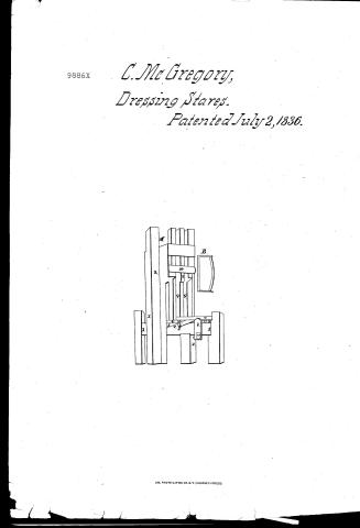
Cyrus McGregory's Patent Drawing for a Stave Dresser

National Archives, Restored Patent Drawings (Record Group 241) · Full-size scan at the National Archives · Catalog record
Show the text on the drawing Hide (19 words)
Words on the drawing as machine-read by the National Archives; not checked. Useful mainly for searching.
ares / un / 1° / of
USPTO scan
The patent as scanned by the USPTO
-
 Page 1
-
 Page 2
-
 Page 3
-
 Page 4


U.S. Patent and Trademark Office · Google Patents
Show the transcription Hide (1,040 words)
Machine transcription (LightOnOCR) of the pages as scanned by the USPTO, most of them the handwritten copies made when the records were restored after the 1836 fire. Not checked; it can misread handwriting, so compare it with the scan.
Page 1.
9886X
C. McGregory,
Dressing Stares.
Patented July 2, 1836.

A.M. PHOTO-LITHO. CO. N.Y. (OSBORNE'S PROCESS)
Page 2.
July 2, 1836
Cyrus M. Gregory of Newport, State of New Hampshire
Title Patent.
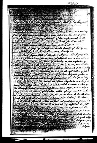
The schedule refers to my above Letter, Patent and making part of the same, containing a description in the words of the said Cyrus M. Gregory himself of his improvement in the mode of making or manufacturing Staves for Barrels, and I will hereon set down these few words that come.
Cyrus M. Gregory of Newport in the County of Sullivan and State of New Hampshire, now being—
Do it known that I the said Cyrus M. Gregory, have invented, constructed, made, and applied to use a new and useful improvement in the mode of making or manufacturing Staves for Barrels, Hogsheads, and any other casks, called the Water Power Stave, described and specified in the words following (1/3)
This improvement consists in the application of perpendicular & horizontal guides & springs to said horizontal guides as more fully explained in the following described machine for driving or driving Staves, Two beams are fixed lengthwise in a horizontal line, parallel to each other, so far apart as to admit a space of the thickness which you wish between their edges, and as long or longer than the width of the Stave which opening must be continued or cut or mortised down through the said beam to let the Stave freely pass after it has passed between said beams, the beams to be firmly fixed to stand on foot at each end or frames in the building where the machine is set up, of sufficient height from the floor for the Stave to fall out, and be finished off. It is known, however, of any convenient length, from six to ten feet more or less, and the beam passes through a frame similar to the same frame on the opposite end, and is to be so placed that the top of the moving frame is in contact with the horizontal guide and the bottom of the moving frame is in contact with the moving frame or made to play—
Page 3.
34.
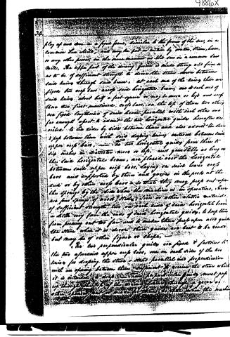
play of one door in a fixed frame, similar to the frame of the saw, in a common saw mills, and may be put in motion by water, steam, horse, or any other power, in the same manner as the saw in a common saw mills. The upper part of the driving frame is made strong and firm so as to be of sufficient strength to drive the staves down between said knives through said beams, at each end of the driving there are fixed two cross bars across said horizontal beams, one at each end of said driving about half a foot square or may be more or less and each have two fixed horizontal cross bars, on the top of them two other are fixed lengthwise of said beams parallel with each other and far enough apart to admit the two horizontal guides hereafter described to be slid by side between them and also admit the two gaps between them with said dropping knives cast on between said upper cross bars. The two horizontal guides from them to dip inches in diameter more or less, and generally as long as the said horizontal beams, are placed over the horizontal between said upper cross bars, laying on said lower cross bars and supported by them and grooves in the posts at the end or by other cross bars so that they may pass out upon the springs by the side when the machine is in operation, there are four springs of wood, steel, iron or other elastic material of sufficient strength two on each side of said horizontal beam a little way from the ends of said horizontal guides, to keep them from passing out too far and to make them proportion and guide the staves when it is done, these guides are best to be round but may be of other figures or shapes.
The two perpendicular guides are fixed & fastened to the two aforesaid upper cross bars, one on each side of the two knives for dropping the staves — made parallel and perpendicular with an opening between them sufficient to receive the staves which it is intended to drop. The said perpendicular guides must pass up through the top of the driving frame through a groove or other opening and so made that it is so that when the machine
Page 4.
9886X
25
in motion they are to lay through the top, the bottom of each guide remaining firm under the two upper ends bars—
made as by a model deposited in the Patent Office of the United States drawing of which is herewith annexed in which Fig 1 represents the frame frame, Fig 2, the driving frame Fig 3 the vertical beam which passes through the driving frame— and Fig 4, Fig 4. Represents the stuffing or covering off of the beam below the driving and cover of which is channeled off that while the stone is driven through the beam the shaving & splintering may fly off at the out side— Fig 5 Represents under cross bars, Fig 6. Represents upper cross bars. Fig 7. Represents horizontal guide, Fig 8. Springs & horizontal guide three times other one being in shape of frame are not here represented Fig 9. The spring guides Fig 10. The cross front of driving frame is held in place and steady upright guides. This improvement then consists in the construction and application of the horizontal guide & springs to them, one of the said upright guides (knives having been heretofore fixed in a beam for dressing stone) to guide, keep in place, steady the stone and stone from breaking when driven.
I do testify that the foregoing is a true specification of my said improvement as above described I have hereunto set my hand this fourteenth day of December A.D. 1833.
Witnesses
Amasa E.
Samuel C. Cleveland
1020 wds
Gym M. Gregory
Drawing
About this record
- Patentee
- Jim Shaw's X-patent list
- Date
- the Name and Date index of patents, USPTO records, Jim Shaw's X-patent list
- Invention
- the Name and Date index of patents
- Listed in
- the Name and Date index of patents, USPTO records, Jim Shaw's X-patent list, Burke's List of Patents (1847)
- Burke's 1847 Patent Office list gives the same patent.