

Drawings and documents
National Archives restored drawings: drawing
Aaron Parson's Patent Drawing for a Machine for Thrashing and Cleaning Grain

National Archives, Restored Patent Drawings (Record Group 241) · Full-size scan at the National Archives · Catalog record
Show the text on the drawing Hide (141 words)
Words on the drawing as machine-read by the National Archives; not checked. Useful mainly for searching.
130. THRASHING. / /2 / Thrashing Machines. / A. Cylinder Machines. / 9880x / DIVISIO'T. / AARON PARSON'S / 9890 X / Trashing and cleaning / Grain. / vol 26 pbog / Gatented 2nd July isole / Jig 1 left side view. a pulley attached to the cylinder b.- - c pulley to drive the seived - epplarley to drive the fan if. / Fig 2 b the chrashing cylinder and concave - d endless slive. g seive. h apror i- seive K road. L. erant / Sig. 3 m pulley attached to the cylinder n pulley to drive the apron h. 0 pulley to give motion to the thin g / p.p. drawers. q bonnet / Tig:1 left side view / Tig.2 Section / to / Patent. office March 29th 1839 / Made under the direction of the Comprom / of Intents in conformity with act 30 have / commissioner of Latents
USPTO scan
The patent as scanned by the USPTO
-
 Page 1
-
 Page 2
-
 Page 3
-
 Page 4


U.S. Patent and Trademark Office · Google Patents
Show the transcription Hide (1,044 words)
Machine transcription (LightOnOCR) of the pages as scanned by the USPTO, most of them the handwritten copies made when the records were restored after the 1836 fire. Not checked; it can misread handwriting, so compare it with the scan.
Page 1.
9890X
J. Parson.
Thrashing Mach.
Patented Jul. 2, 1836.
Fig. 1. Left side view
Fig. 2. Section
Fig. 3. Right side view
Page 2.
9890x
July 2, 1836
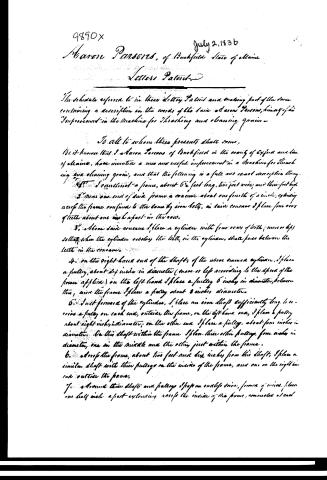
Aaron Parsons, of Bushfield State of Maine
Letters Patent
The schedule referred to in these Letters Patent and making part of the same containing a description in the words of the said Aaron Parsons, himself of his "Improvement in the Machine for Thrashing and Cleaning Grain."
To all to whom these presents shall come,
Be it known that I Aaron Parsons of Bushfield in the county of Oxford and State of Maine, have invented a new and useful improvement in a Machine for Thrashing and Cleaning Grain, and that the following is a full and exact description thereof.
1. I construct a frame, about 6½ feet long, two feet wide, and three feet high.
2. Near one end of said frame a cone about one fourth of a circle, extending across the frame, confined to the same by iron bolts, in said cone I place four rows of teeth about one inch apart in the row.
3. Above said cone I place a cylinder with four rows of teeth (more or less) so that when the cylinder revolves the teeth, in the cylinder, shall pass between the teeth in the cone.
4. On the right-hand end of the shaft of the above named cylinder, I place a pulley, about 4½ inches in diameter (more or less according to the speed of the power applied). On the left hand I place a pulley 6 inches in diameter, between this, and the frame I place a pulley about 3 inches diameter.
5. Just forward of the cylinder, I place an iron shaft sufficiently long to receive a pulley on each end, outside the frame, on the left hand end, I place a pulley about eight inches in diameter; on the other end I place a pulley about four inches in diameter. On this shaft within the frame I place three other pulleys, four inches in diameter, one in the middle and the other just within the frame.
6. Above the frame, about two feet and six inches from this shaft, I place a similar shaft with three pulleys on the inside of the frame, and one on the right hand end outside the frame.
7. Around these shafts and pulleys I place an endless rope, formed of wires, place one half inch apart extending across the inside of the frame, connected at each
Page 3.
9890X
July 2, 1836
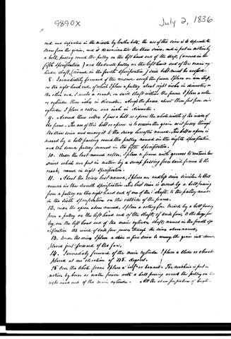
and and supported in the middle by leather belts, the use of this sieve is to separate the straw from the grain, and is denominated the straw sieve, and is put in motion by a belt; passing round the pulley on the left hand end of the shaft; (named in the fifth specification) and the small pulley on the left hand end of the main cylinder shaft, (named in the fourth specification) said belt must be crossed.
8. Immediately forward of the sieve above the frame I place an iron shaft, on the right-hand end, of which I place a pulley about eight inches in diameter; on the other end, I make a crank, on said shaft within the frame I place a roller or cylinder three inches in diameter. Above the frame, about three feet from said cylinder I place a roller one inch in diameter.
9. Around these rollers I pass a belt or apron the whole width of the inside of the frame. The use of this belt or apron is to receive the grain as it passes through the straw sieve and convey it to the sieves hereafter named. This belt or apron is moved by a belt passing round the pulley named in the eighth specification, and the second pulley named in the fifth specification.
10. Under the last-named roller, I place a frame with grooves to contain two sieves which are put in motion by a screw passing from said frame to the crank, named in eight specification.
11. About the sieves last named, I place an endless sieve similar to that named in the seventh specification. This last sieve is moved by a belt passing from a pulley on the right-hand end of one of the 7 shafts, to the pulley named in the eighth specification on the outside of the frame.
12. Under the apron above named, I place a rotary fan, moved by a belt passing from a pulley on the left-hand end of the shaft, of said fan, to the large pulley, on the left-hand end of the main cylinder shaft; named in the fourth specification the wind of said fan passes through the sieves above named,
13. Under the sieve I place a stone or fine sieve to convey the grain into clean, placed just-forward of the fan,
14. Immediately forward of the main cylinder I place a stone or elevator placed at an elevation of 45 degrees.
15. Over the whole frame I place a roof or bonnet. The machine is put in motion by horse or water power with a belt passing round the pulley on the right hand end of the main cylinder. All the above specifications of length -
Page 4.
9890x
July 2, 1836
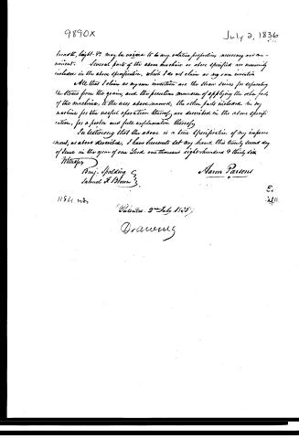
breadth, height &c may be varied to any suitable proportion necessary and convenient. Several parts of the above machine as above specified are necessarily included in the above specification, which I do not claim as my own invention.
All that I claim as my own invention are the straw sieves for separating the straw from the grain, and the peculiar manner of applying the other parts of the machine, to the uses above named, the other parts included in my machine for the useful operation thereof are described in the above specification, for a fuller and full explanation thereof.
In testifying that the above is a true specification of my improvement, as above described, I have hereunto set my hand this twenty second day of June in the year of our Lord one thousand eight hundred and thirty six.
Witness
Benj. Spalding
Samuel H. Brown
Narson Parsons
11841 22
Patented 2 July 1836
D. A. W.
Published accounts: journal notice
Notice in the monthly list of patents
Journal of the Franklin Institute, new ser., vol. 18 (1836), p. 359 · View the page
582. Trashing machine. Aaron Parsons, Rockfield, Maine.
About this record
- Patentee
- the Journal of the Franklin Institute, Journal
- Date
- the Name and Date index of patents, USPTO records, Jim Shaw's X-patent list
- Invention
- the Name and Date index of patents
- Listed in
- the Name and Date index of patents, USPTO records, Jim Shaw's X-patent list, the Journal of the Franklin Institute, Burke's List of Patents (1847)
- The patentee's full name comes from the Franklin Institute's journal.
- Burke's 1847 Patent Office list gives the same patent.