

Drawings and documents
National Archives restored drawings: drawing
Almon Roff's Patent Drawing for a Sliding Ward Lock

National Archives, Restored Patent Drawings (Record Group 241) · Full-size scan at the National Archives · Catalog record
Show the text on the drawing Hide (38 words)
Words on the drawing as machine-read by the National Archives; not checked. Useful mainly for searching.
70. : / 70. LOCKS à LATON / [93] / Pivotod Tumbier. / Saha / ALMOUN The OFFS Pulent sliding Ward Books / is / #2 - / Patented / CLASSIFICATION / 9893. 4 / page 25. / DIVISION. / 9893 / (o) / IIII / IT / -A
USPTO scan
The patent as scanned by the USPTO
-
 Page 1
-
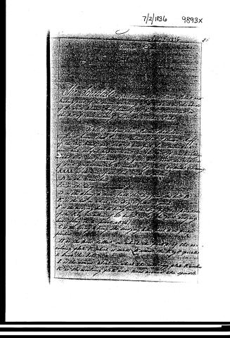 Page 2
-
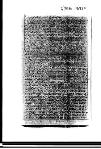 Page 3
-
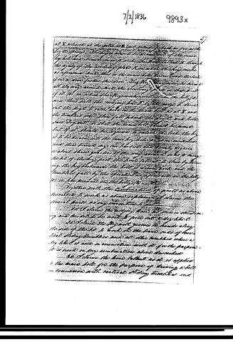 Page 4
-
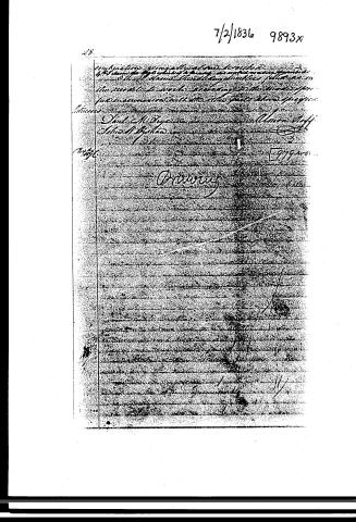 Page 5


U.S. Patent and Trademark Office · Google Patents
Show the transcription Hide (832 words)
Machine transcription (LightOnOCR) of the pages as scanned by the USPTO, most of them the handwritten copies made when the records were restored after the 1836 fire. Not checked; it can misread handwriting, so compare it with the scan.
Page 1.
No Printed Specification Available
9893X
A. Roff,
Lock.
Patented July 2, 1836

A.M. PHOTO-LITHO. CO. N.Y. (OSBORNE'S PROCESS)
Page 2.
7/2/1836 9893x
July 2, 1836
The chocolate experiment in the line. I was not making use of the time in any way, and I was thinking of the one which I had left off the day before. I was not making use of the time in any way, and I was thinking of the one which I had left off the day before.
I will now tell you the whole story.
A is the line which I had left off …
Page 3.
7/2/1836 9893x
I now wish the level of the by-stone
I is the line in which the level is placed
W represents any number of lines and the by-stone
O is the by-stone the work is to be done to the maximum
and working plan in this place
P is the by-stone with a small spring
no different in style and not intending to be back of the
to which is added
But a small spring is added to the by-stone (to 13)
to take the by-stone to the by-stone position to let the
by-stone operate upon the by-stone by a different by-stone
long or little to the by-stone and then in order to make the
further
S is a guide for the by-stone
T is the by-stone to which the level of the by-stone
W is the by-stone by-stone
W is a guide for the by-stone to let it go upon the by-stone
like when the by-stone is then put into place by the
Tang the by-stone and explain the plan of which
from of which parts are made and how to use our
claim. I claim the combination of the parts of which
is to be used in the method of driving a by-stone and
with the by-stone as follows:
1. That the by-stone P is a by-stone in the usual
manner and known to parts of the by-stone
this by-stone though the by-stone is not a by-stone by
being made to by-stone of the by-stone and the
to be put into the by-stone upon the by-stone to
unplug the by-stone to be put into the by-stone
the by-stone of the by-stone the by-stone to
Page 4.
7/2/1836 9893x
at X released at the other end and subsequently back as far as the D, a spring. The key is now to be drawn out of the main key hole and turned so as to slide the lock so that it, though the key of the locking plate has been withdrawn, the key works as a primary. Now this is the main bolt, then turn the lock if on a wire, push the key. The key is drawn out, the turn all the way around and the locking plate is then put of 10 (1) in which the key works until it hits the key (2) and thus with the keying back by the way, it turns out the key. It next hits the thumb bolt as at X and the thumb bolt then falls behind the key (2) and falls into D, so that the main bolt should be moved but if it should be required to unlock the lock, the key is to be drawn out, the main key hole, and then withdrawn and thus turned by the hand and twenty degrees or about three quarters of the way around, so as to swing the bit of the key, put the lock, fall out, it then follows, the key is drawn, the bolt is drawn back and the thumb bolt falls by the operation of the main bolt (2) in the manner in the key (1).
Together with the combination of parts as above described to work as above explained, I claim the several parts as my invention and I will
1st claim the keying bars as seen in the drawing and the slot to be used to pass into D by the C.
2nd claim the key with grooves in hands along the side of the bit to lock into the base ends of two fixed sliding tumblers and all other tumblers where a key like C is used in connection with it for the purpose. It is used in my combination above described.
3rd claim the hand bolt as it is applied to the main bolt for the purpose of having a bolt in connection with vertical sliding tumblers and
Page 5.
7/2/1836 9893x
28.
combining great and small bodies.
The change of this body being so very remarkable
that it seems the body is filled as in
the middle is made according to the mode of
production with the other parts of the region.
Moses
Jul. 1836
Union Staff
[9794]
Ottawa
Published accounts: journal notice
Notice in the monthly list of patents
Journal of the Franklin Institute, new ser., vol. 18 (1836), p. 359 · View the page
547. Locks for doors, &c.-Almon Roff, N. Y.
About this record
- Patentee
- the Journal of the Franklin Institute, Journal
- Date
- the Name and Date index of patents, USPTO records
- Invention
- the Name and Date index of patents
- Listed in
- the Name and Date index of patents, USPTO records, Jim Shaw's X-patent list, the Journal of the Franklin Institute, Burke's List of Patents (1847)
- The sources give different dates; the date shown is the one most of them agree on.
- The patentee's full name comes from the Franklin Institute's journal.
- The residence comes from the Franklin Institute's journal.
- The Franklin Institute's journal confirms the date shown.
- Burke's 1847 Patent Office list gives the same patent.
- Burke's 1847 Patent Office list gives a slightly different date; the date shown follows the standard lists.