

Drawings and documents
National Archives restored drawings: drawing
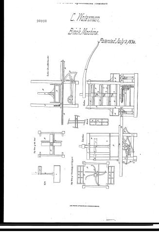
Calvin Waterman's Patent Drawing for an Improved Brick Making Machine

National Archives, Restored Patent Drawings (Record Group 241) · Full-size scan at the National Archives · Catalog record
Show the text on the drawing Hide (65 words)
Words on the drawing as machine-read by the National Archives; not checked. Useful mainly for searching.
Brick Machines, / Portable Mold: In Carrier, / Approached transverse to feed. / DIV. 15 / CLASS / Top of the I'lb / 9899-1 / DDI V / 9899 X / Gate / Section thro' the Chamber / Top view of Chambersg; Dischargers / Side / Section / Mould / Calvin Waterman's / Improved Brick Making / Machine / Patented 2 July 1836 / Copied from Drawing attached / 10 Patent . Oct.20 1853 / 6.
USPTO scan
The patent as scanned by the USPTO
-
 Page 1
-
 Page 2
-
 Page 3
-
 Page 4


U.S. Patent and Trademark Office · Google Patents
Show the transcription Hide (905 words)
Machine transcription (LightOnOCR) of the pages as scanned by the USPTO, most of them the handwritten copies made when the records were restored after the 1836 fire. Not checked; it can misread handwriting, so compare it with the scan.
Page 1.
9899X
C. Waterman,
Brick Machine.
Patented July 2, 1836.

AM. PHOTO-LITHO. CO. N.Y. (OSBORNE'S PROCESS)
Page 2.
7/2/1836 9899X
382. July 2-36
Calvin Waterman
Bath Maine
Letters Patent
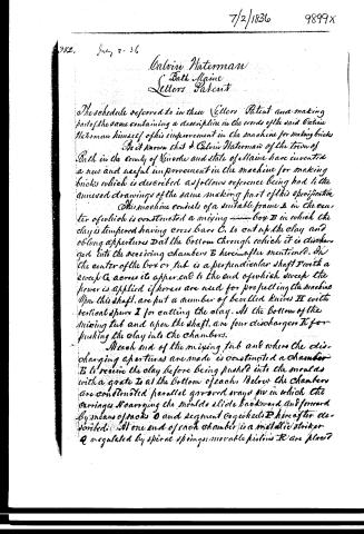
The schedule referred to in these Letters Patent and making part of the same containing a description in the words of the said Calvin Waterman himself of his improvement in the machine for making bricks.
Be it known that I, Calvin Waterman of the town of Bath in the county of Aroostook and state of Maine have invented a new and useful improvement in the machine for making bricks which is described as follows reference being had to the annexed drawings of the same making part of this specification.
This machine consists of a suitable frame A in the center of which is constructed a mixing box B in which the clay is tempered having cross bars C, to cut up the clay and oblong apertures D at the bottom through which it is discharged into the receiving chambers E hereinafter mentioned. In the center of the box or tub is a perpendicular shaft F with a sweep G across its upper end to the end of which sweep the power is applied if horses are used for propelling the machine upon this shaft, are put a number of bevelled knives H with vertical spurs I for cutting the clay. At the bottom of the mixing tub and upon the shaft, are four dischargers K for pushing the clay into the chambers.
At each end of the mixing tub and where the discharging apertures are made is constructed a chamber E to receive the clay before being pushed into the moulds with a grate I at the bottom of each. Below the chambers are constructed parallel grooved ways J in which the carriages N carrying the moulds slide backward and forward by means of racks O and segment or wheels P hereafter described. At one end of each chamber is a metallic striker Q regulated by spiral springs; movable pistons R are placed
Page 3.
in the moulds for facilitating the discharge of the bricks. The pressure is given by means of a large cog wheel S at the bottom of the perpendicular or main shaft. B working into a small vertical cog wheel T fixed on a horizontal shaft. U having on its end a crank V from the wrist of which leads a connecting rod W to short bar X connected together forming a toggle joint one end of which works in a permanent concave block Y at the foot of the frame — the other end is attached to one end of a lever a turning and bolt or pin b the other end of the lever being attached to the rod C of the piston screws are placed at the end of the toggle joint where it is connected with the lever for regulating the pressure of the brick and when the crank has turned so far as to straighten the toggle joint the maximum of power is obtained raising the end of the lever a and depressing the other end of said lever and with it the piston d and thus pressing the clay through the gate into the moulds; whilst this operation is going on that of closing the discharging aperture by the gate e is effected by means of a connecting of levers f and rods g with the same power causing the gate to be closed before the piston has arrived at the bottom of the chamber and whilst the pressing is effected the carriage is moved back for an empty mould and as it advances with this mould the piston raises, the filled mould is pushed forward and the empty one takes its place: this is accomplished by means of another crank shaft and cog wheel in connection with a segment cog wheel and rod the cog wheel being turned by the first mentioned vertical cog wheel working into it. This turns the crank shaft from whose wrist extends a connecting rod attached to the segment cog wheel which is made to vibrate to the right or left at the same time it works in the track under the carriage causing it to pass in and out from under the chamber. Whilst the carriage is running in the piston and gate are raising and the clay is passing into the chamber produced by the revolving motion of the discharges.
Page 4.
7/2/1836 9899X
384.
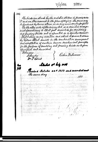
The bricks are struck by the metallic striker in passing under it and are then removed to the place of drying. The power may be produced by horses, steam, or in any mode preferred. On the other side of the mixing tub is a similar arrangement of machinery to that just described for moulding and pressing bricks and is operated in a similar manner. What I claim as my invention and which I desire to secure by Letters Patent consists in the combination arrangement and adaptation of certain known mechanical principles for the purpose of moulding and pressing bricks as before specified and described.
Witnesses
A. Snyder
Wm. P. Elliot
Eulow Waterman
Issued October 22, 1853 and recorded on the same day 1084
Published accounts: journal notice
Notice in the monthly list of patents
Journal of the Franklin Institute, new ser., vol. 18 (1836), p. 359 · View the page
569. Brick machine. Calvan Waterman, Bath, Maine.
About this record
- Patentee
- the Journal of the Franklin Institute, Journal
- Date
- the Name and Date index of patents, USPTO records, Jim Shaw's X-patent list
- Invention
- the Name and Date index of patents
- Listed in
- the Name and Date index of patents, USPTO records, Jim Shaw's X-patent list, the Journal of the Franklin Institute, Burke's List of Patents (1847)
- The patentee's full name comes from the Franklin Institute's journal.
- Burke's 1847 Patent Office list gives the same patent.