

Drawings and documents
National Archives restored drawings: drawing
J. Turk's Patent Drawing for a Smut Machine

National Archives, Restored Patent Drawings (Record Group 241) · Full-size scan at the National Archives · Catalog record
Show the text on the drawing Hide (34 words)
Words on the drawing as machine-read by the National Archives; not checked. Useful mainly for searching.
83. MILLS. / In / Grain Scourers. / Cylinder, Horizontal. / classFrication / 92354 / DIVIDIO*T / 9235 X / As / Lmut Machine. / Fat: / àc / F.B.del:
USPTO scan
The patent as scanned by the USPTO
-
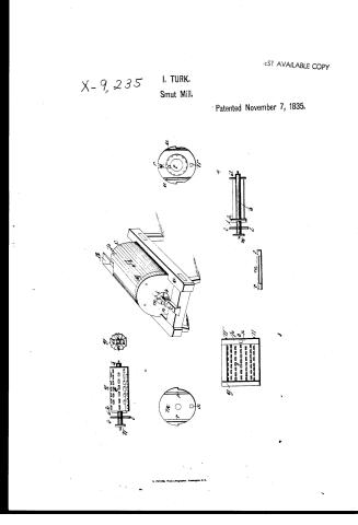 Page 1
-
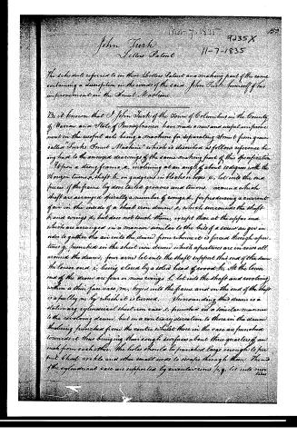 Page 2
-
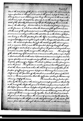 Page 3
-
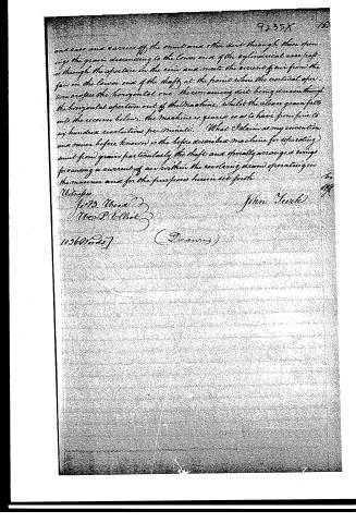 Page 4


U.S. Patent and Trademark Office · Google Patents
Show the transcription Hide (1,057 words)
Machine transcription (LightOnOCR) of the pages as scanned by the USPTO, most of them the handwritten copies made when the records were restored after the 1836 fire. Not checked; it can misread handwriting, so compare it with the scan.
Page 1.
X-9,235
I. TURK.
Smut Mill.
Patented November 7, 1835.
BEST AVAILABLE COPY
N. PETER, Photo-Lithographer, Washington, D.C.
Page 2.
Nov 7, 1835 9035 X 159
John Turk
Letters Patent 11-7-1835
The schedule referred to in these Letters Patent and making part of the same containing a description in the words of the said John Turk himself of his improvement in the Smut Machine.
Be it known that I John Turk of the Town of Columbus in the County of Warren and State of Pennsylvania have made a new and useful improvement in the useful arts, being a machine for separating Smut from grain called "Turk's Smut Machine" which is described as follows reference being had to the annexed drawings of the same making part of this specification.
Upon a strong frame, a, inclining at an angle of about 10 degrees with the horizon turns a, shaft b, on guigeons in blocks or boxes c, let into the end pieces of the frame by dovetailed grooves and tenons, around which shaft are arranged spirally a number of wings, d, for producing a current of air in the inside of a sheet iron drum, e, which surrounds the shaft b and wings d, but does not touch them, except that at the upper end which are arranged in a manner similar to the bits of a screw auger in order to gather the air into the drum from whence it is forced through apertures, g, punched in the sheet iron drum, which apertures are in rows all around the drum, four arms let into the shaft support this end of the drum, the lower end, i, being closed by a solid head of wood, k. At the lower end of the drum are four or more wings, l, let into the shaft and revolving within a thin fan case, m, keyed into the frame and on the end of the shaft is a pulley, n, by which it is turned. Surrounding this drum is a stationary cylindrical sheet iron case, o, punched in a similar manner to the revolving drum, but in a contrary direction to those in the drum, the latter being punched from the centre whilst those in the case are punched towards it thus bringing their rough surfaces about three quarters of an inch from each other. The holes should be punched large enough to permit dust, cockle and other small seeds to escape through them. The ends of the cylindrical case are supported by circular rims, p, q, let into my box.
Page 3.
tins in the side pieces of the frame secured by screws, the upper one having an aperture a, through it to admit the grain to pass between the revolving drum, and stationary case being also covered at the end with a sheet iron cap. S except an opening t, in the centre as large as the circle of the spirally placed wings t' for the passage of the air into the drum, the other wing has two ribs, u, on its outer side fitting into grooves in the fan case V, which case closes the lower end of the cylindrical case. At the end of the cylindrical case and through the rim is an aperture w, communicating with another aperture x, in the bottom of the fan case having a branch aperture from the before mentioned aperture running vertically and at right angles with a horizontal aperture in the rim—the vertical aperture being for the discharge of the cleaned grain into a receiver below and the horizontal opening being for the escape of the chaff or dust which is separated from the grain as it meets the current of air created by the wings within the fan case. The upper half of the stationary cylindrical case is covered with a plain cap A, of iron or sheet iron nailed to the rims to prevent, in consequence from dust having an aperture in it corresponding with the one in the upper rim for the reception of the end of a hopper B, which is placed over this opening to receive the grain. The cylinder or revolving drum has oblong openings in it at the lower end made where the sheets of iron come together for the purpose of suffering any grain to pass out that may have insinuated itself during the operation of the machine and a notch opening should be made in the same direction that the cylinder revolves for the more easy cleaning itself of the same. The machine being put in operation by the band from the driving power passing around the pulley on the end of the shaft, the grain to be cleaned from smut is put into the hopper from whence it passes along the opening or spout in the rim and enters between the revolving drum, and stationary case, the rough surfaces of which coming nearly together break the smut and escape the grain at the same time. The current of air caused by the spirally placed wings on the shaft and the straight wings in the centre of the drum, forces the air through the punched holes in the drum and case and
Page 4.
and case and carries off the dust and other dirt through these openings the grain descending to the lower end of the cylindrical case passes through the aperture in the rim and meets the current of air from the fan on the lower end of the shaft at the point where the vertical aperture crosses the horizontal one, the remaining dirt being drawn through the horizontal aperture out of the machine, whilst the clean grain falls into the receiver below, the machine is geared so as to have from five to six hundred revolutions per minute. (What I claim as my invention and never before known) is the before described machine for separating dust from grain particularly the shaft and specially arranged wings for causing a current of air within the revolving drum operating in the manner and for the purposes herein set forth.
Witnesses
J. B. Wood
Wm. P. Elliot
John Suck
10360 Words] (Drawing)
Published accounts: journal notice
Notice in the monthly list of patents, with remarks
Journal of the Franklin Institute, new ser., vol. 17 (1836), p. 405 · View the page
9. For a Smut Machine; John Tuck, Columbus, Pennsylvania, November 7.
Remarks. There is a stationary cylinder of sheet-iron standing on a suitable frame, its axis being inclined at an angle of about ten degrees with the horizon. Within this cylinder there is a second, which is made to revolve, the two being about three-fourths of an inch apart. They are both punched, grater fashion, their rough surfaces being towards each other. Within the inner cylinder there is a revolving fan wheel, extending its whole length. The grain is fed in at the upper end, between the two cylinders; the revolving of the inner one rubs the grain, whilst the wind from the fan, blowing through the apertures, discharges it, together with the cheat and cockle, the openings in the outer cylinder being made large enough for that purpose. The claim is to the machine generally, and "particularly to the shaft and spirally arranged wings for causing a current of air within the revolving drum."
Published accounts: journal notice
Notice in the monthly list of patents (listed with a different spelling or date)
Journal of the Franklin Institute, new ser., vol. 17 (1836), p. 144 · View the page
Smut Machine. John Tuck, Columbus, Pennsylvania,
About this record
- Patentee
- Jim Shaw's X-patent list
- Date
- the Name and Date index of patents, USPTO records, Jim Shaw's X-patent list
- Invention
- the Name and Date index of patents
- Listed in
- the Name and Date index of patents, USPTO records, Jim Shaw's X-patent list, the Journal of the Franklin Institute, the Journal of the Franklin Institute, Journal, Burke's List of Patents (1847)
- Also listed in a contemporary journal or list under a different spelling or date; the record shown follows the standard lists.
- Burke's 1847 Patent Office list gives the same patent.