

Drawings and documents
National Archives restored drawings: drawing
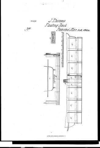
John Thomas' Patent Drawing for a Floating Dock

National Archives, Restored Patent Drawings (Record Group 241) · Full-size scan at the National Archives · Catalog record
Show the text on the drawing Hide (106 words)
Words on the drawing as machine-read by the National Archives; not checked. Useful mainly for searching.
Peen Halsh Coulter of Inw Thomas / OLASS 114. SHIPS / 51, Camels & Floating Decks. / John Thomas / CLASSI ICATION / 8109- X / Floating Dock. / DIVISION. / Patented March 26th 1834 / References: / A Side view of a truss Irame for the partition to be spiked to / B Profile of a floate and wells & the manner of using well- floats / C, Midship section of a Steam boat / D, The Pumps and the Pendulum brake. / EEEE &c. Profile of the of Dock & a Steam boat. / Scale 20 of feet / 25 / 30 / C= / P1 / PIA / C.L. Fleischmann Civil Engineer.
USPTO scan
The patent as scanned by the USPTO
-
 Page 1
-
 Page 2
-
 Page 3
-
 Page 4
-
 Page 5
-
 Page 6
-
 Page 7
-
 Page 8
-
 Page 9
-
 Page 10
-
 Page 11
-
 Page 12
-
 Page 13
-
 Page 14
-
 Page 15
-
 Page 16
-
 Page 17
-
 Page 18
-
 Page 19
-
 Page 20
-
 Page 21
-
 Page 22
-
 Page 23
-
 Page 24
-
 Page 25
-
 Page 26
-
 Page 27
-
 Page 28
-
 Page 29


U.S. Patent and Trademark Office · Google Patents
Show the transcription Hide (10,657 words)
Machine transcription (LightOnOCR) of the pages as scanned by the USPTO, most of them the handwritten copies made when the records were restored after the 1836 fire. Not checked; it can misread handwriting, so compare it with the scan.
Page 1.
8109X
J. Thomas.
Floating Dock.
Patented Mar. 26, 1834.
Nº

Page 2.
March 26, 1834
John Thomas.
Letters Patent.
The Schedule, referred to in these Letters Patent and making part of the same, containing a description in the words of the said John Thomas himself of his improvement in the Floating Dry Dock for repairing Steam Boats and other Vessels which invention he has assigned in accordance with law to James H. Peck, William Thomas, Robert Nash, and John D. Couller, all of the State of Missouri, which assignment is recorded in the Patent Office, in the Book of transfers, Vol. 5, from page 87 to page 98.
The Floating Dry Dock as it is improved by the said invention of the said Thomas, will be hereinafter called the improved Floating Dry Dock. It is intended to float in and upon the water. It is capable of being sunk and suspended with its deck at any depth beneath the surface of the water, which may be necessary for the purpose of admitting the vessel which is to be repaired whilst it is drawing its full draft of water to be floated over the cradle on which it is to be raised, and which is constructed on the deck of the dock. It is then capable when the vessel shall have been floated over its cradle of being made to rise, and take her with necessity upon the cradle, and to continue to rise slowly until its deck shall appear above the water as high as may be necessary to preserve it dry, and to bear and sustain the vessel which is on its cradle as far above the deck of the dock as shall be necessary for all the purposes of making repairs upon her with convenience. The vessel which is to be repaired may be in this manner raised and sustained upon the improved floating dry dock without being in danger of being strained or injured and will be exposed, on every part of her external surface,
Page 3.
to either bottom, sides or ends, to light and to the action of the air. This improved Floating Dry Dock, may be composed of one or more floats. To describe the said new and useful improvements and the manner of using the same, in terms so full clear and exact as to distinguish them from all other things before known, and to enable any person skilled in the art to which they relate, or of which they are branches or with which they are most nearly connected to make and use the same and to explain fully the principles of said inventions and the several modes in which the said Thomas has contemplated the application of those principles by which they and the character of those inventions may be distinguished from all others. I will describe the improved floating dock in one of its forms and proportions, and the manner in which it is constructed, and point out as they may be contained therein, and describe as they may be illustrated therefrom, the said new and useful improvements and the manner of making and using the same. The one here will describe shall be composed of nine floats. Each of these floats, has sides, ends, a bottom and a flush deck, and on its extreme surface is about sixty two feet in length, about fourteen feet in breadth and about four feet six inches in depth, this depth being the length of a line drawn perpendicularly between the external surfaces of its deck and bottom. Each of the sides and ends of each float, has externally a perpendicular plane surface, the bottom and also the deck of each float has externally a horizontal plane surface. The sides of each float are parallel to each other. The ends of each float are at right angles with the sides. The floats as they form the dock are all ranged together side to side and fastened to each other. Their ends form the sides of the dock. The dock is thus made to form a rectangular parallelogram the longer lines of which are at right angles with the longer lines of the parallelogram formed by each float. The deck of the dock is formed by the decks of the floats. The ends
Page 4.
of the dock, or that which is constructed on the dock for the purpose of holding the vessel, which is to be repaired, sufficiently above the deck of the dock for the repairs to be made with convenience, is in detached parts and is distributed equally to the decks of the several floats. Each float has a tank on each of its ends which rises about twelve feet above the deck and is on its external surface about twelve feet in width on two of its parallel sides by about three feet on its other two sides, the broader sides of the tank are at right angles with its narrower sides, and are parallel to the ends of the floats, and extend across its interior. The interior of each float is divided into four chambers nearly equal in size, by partitions or bulk heads, which partitions are perpendicular and are at right angles with the longer sides of the float. The interior of each tank is divided into three apartments by perpendicular partitions at right angles with the broader sides of the tank which apartments will be denominated wells. The center apartment of each tank will be called the pump well. Each of the float wells in the interior is about two feet nine inches square in the clear. The interior of each tank on that side nearest the end of the float, is on the same perpendicular plane with the inner side of the end timbers of the float. There are two common fixed iron pumps fourteen feet and a half in length in each pump well, by which the water is to be drawn from chambers of the floats when the dock is to be raised. There is in each float what will be denominated a well float, which on its external surface is two feet seven inches square by five feet in length. This well float is made light to give it great buoyancy in the water. The sides of each one of the nine floats is twelve inches thick made of solid timbers. Their ends and also the narrower sides of each tank are nine inches thick of solid timbers. The timbers of each side of each float, are strongly fastened together by strong iron bolts three quarters of an inch square which are driven through one piece of timber, and into the one next below it to the depth of about
Page 5.
ten inches in two rows along from end to end of the side timbers and within about one fourth part of the thickness of the sides from the outside of these timbers and within about one third part of their thickness from the inside of them. The outside bolts are driven within about four feet of each other, the inside bolts within about eight feet of each other. Those towards the outside being driven at about an angle of eighteen degrees from a perpendicular line pointing neither towards the inside nor towards the outside of the timbers, but alternately towards each end of the float so that in their relation to each other they form a sort of dovetail for the purpose of giving strength to these fastenings; those towards the inner side of the timbers, are driven alternately with the same inclination and for the same purpose. The timbers of each end of each float are fastened to each other with like bolts, driven in like manner in reference to their inclination and their distances from each other, and their depth into the other timbers into which the bolts pass. The bolts in the end timbers are driven on each side within one third part of the thickness of the end timbers, of the edges of the timbers. Each of the narrower sides of the tank is a solid piece of timber. The deck and bottom of each float and also the partitions of the interior of each float are two inches in thickness. No partitions obstruct the communication between the walls of the tanks and the chambers of the floats. The timbers of the ends of each float are strongly united to the timbers of the sides at the corners of the float by a rabbit joint, the rabbit of which is cut exclusively in the timbers of the sides. This rabbit being six inches each way, that is, in width and depth, and by iron bolts of the dimensions mentioned driven horizontally through the timbers of the ends into the timbers of the sides and also through the timbers of the sides, into the timbers of the ends, in such manner, that the bolts as they cross each other will make an angle towards the interior of the float of about one hundred and seven degrees.
Page 6.
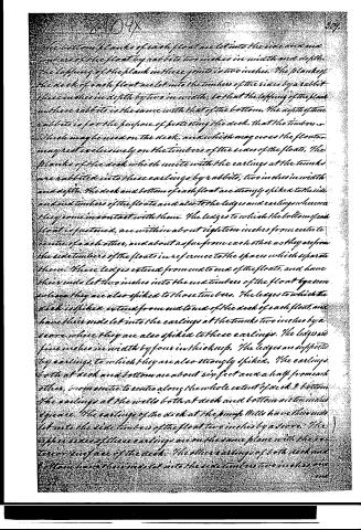
The bottom planks of each float are let into the side timbers of the float by rabbits two inches in width and depth. The lapping of the plank in these joints is two inches. The planks of the deck of each float are let into the timbers of the sides by a rabbit three inches in depth by two in width, so that the lapping of the plank in these rabbits is the same with that of the bottom. The depth of these rabbits is for the purpose of protecting the deck, that the timbers, which may be used on the deck, and which may cross the floats, may rest exclusively on the timbers of the sides of the floats. The planks of the deck which unite with the earlings at the tanks are rabbited into these earlings by rabbits, two inches in width and depth. The deck and bottom of each float are strongly spiked to the side and end timbers of the floats and also to the ledges and earlings wherever they come in contact with them. The ledges to which the bottom of each float is fastened, are within about eighteen inches from each other, and about as far from each other as they are from the side timbers of the floats in reference to the spaces which separate them. These ledges extend from end to end of the floats, and have their ends let two inches into the end timbers of the float by a score where they are also spiked to those timbers. The ledges to which the deck is spiked extend from end to end of the deck of each float, and have their ends let into the earlings at the tanks two inches by a score where they are also spiked to these earlings. The ledges are five inches in width by four in thickness. The ledges are supported by earlings to which they are also strongly spiked. The earlings both at deck and bottom are about six feet and a half from each other, in one end to the other along the whole extent of deck & bottom. The earlings at the walls both at deck and bottom are two inches square. The earlings of the deck at the pump wells have their ends let into the side timbers of the float two inches by a score. The upper sides of these earlings are on the same plane with the exterior surface of the deck. The other earlings of both deck and bottom have their ends let into the side timbers two inches by a score.
Page 7.
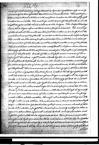
end of each earling being chased in by a horizontal sweep, and by means of a horizontal mortise in these timbers. The earlings, or other than those at the wells are four inches in thickness by eight inches in width. The earlings extend across the floats, and at right angles with their sides and the ledges. The ledges or earlings have their edges up and their sides perpendicular. The earlings of the deck at the wells are two feet two inches and a half from the end timbers of the floats, and have their sides which front upon the wells on the same perpendicular line with the inner side of those sides of the timbers most remote from the ends of the floats. The partitions which divide each float into four chambers are strongly spiked to three frames, made for the purpose of strengthening the floats. Each of these three frames is made of two upright timbers, eight inches thick by ten in width, extending from plank to plank between the deck and bottom and strongly fastened by bolts of iron of the size mentioned to the side timbers of the float, their inner or inner sides being against those timbers, and of horizontal timbers four inches thick by eight in width which stand in the place of earlings and support the ledges as such, which horizontal timbers are strongly spiked to and let at each end into the upright timbers four inches by a score, having as the other earlings their sides perpendicular. Two timbers of the same dimensions with these last pass diagonally from corner to corner of the interior of this frame crossing each other at the centre, these of, at which point they are let half into each other. These timbers have their broader sides at right angles with the horizontal timbers of the frame, and are at each of their ends let into the upright timbers so far in merely as to give them a square shoulder against which to bit, which shoulder is at right angles with their edges and sides. These frames are further strengthened by perpendicular studs which are let into the horizontal and diagonal timbers by a slip lap at the distance of about four feet from each other, to which they are also strongly spiked, which
Page 8.
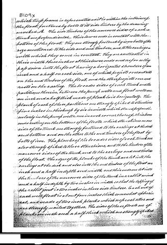
which truss frame is represented as it is within the interior of the float, fastened by bolts to its side timbers by the drawing marked A. The side timbers of the narrower sides of each truss are perpendicular. Their lower ends in contact with the bottom of the float. They are strongly fastened by iron bolts of the size mentioned to the side and end timbers, and to the earlings on which they come in contact. They are contracted in their width three inches at their lower ends and as far as they lap down into the float having a horizontal shoulder of an inch and a half on each side, one of which projects over and sits on the end timbers of the float, and the other projects over and rests on the earling. The broader sides of each truss and the partitions therein, between the pump wells and flood wells are an inch and a half thick made of plank laid horizontally. The plank of each of these partitions are strongly spiked to stanchions five inches in thickness by six in width which stand perpendicularly in the pump wells, one in each corner thereof, their lower ends resting on the bottoms of the floats, which stanchions on one side of the truss are strongly fastened to the earlings at the deck and bottom and on the other to the end timbers of the float by bolts of iron. The planks of the broader sides of each truss are also strongly spiked to these stanchions, and to the timbers of the narrower sides of the truss, and to the earlings and end timbers of the float. The edges of the planks of the truss are let into the earlings at the deck and also into the end timbers of the float an inch and a half in depth and width, and their ends are let into the timbers of the narrower sides of the truss in a rabbit an inch and a half in depth by two inches in width so that the lapping of the rabbit joint is two inches in these side timbers. Each end of each well float is about four inches thick somewhat spherically, and made of two inch planks which stop each other and are strongly nailed together. The sides of these floats are of plank an inch and a half thick which are strongly spiked to
Page 9.
to the inside in a little more in these an inch and a half in width and in depth, and also strongly spiked to frames which are within the well floats, in each of which there are two frames made of plank an inch and a half thick by three inches in width, the sides of the planks of which frames are parallel to the ends of the floats which contain them, and their upper fit against the planks of the sides of the same floats. These frames are at equal distances from each other and from the ends of the floats which enclose them. The planks of the sides of these well floats are also strongly nailed to each other from one end of the float at each corner thereof. The planks of the frames within the well floats are strongly put together by halving them into each other and by nails. The planks of the sides of these floats are laid lengthwise with the floats and are perpendicular, their ends up and down when the floats are in their place. The well float in each well is movable up and down into well and foremost. A strong eye bolt of iron passes through each well float from end to end in the centre of the ends, and is fastened by a nut and screw at the upper end of the float, the eye being at the lower end. The space of the exterior of the well floats is two inches less than the space of the interior of the float walls. A rope or chain made fast in the eye of the bolt at the lower end of the well float passes immediately under a strong timber toward that end of the narrow sides of the tank which is nearest to it, and upon the inside of the well in a groove made in each side for it, to the top of the tank and over its top and down on the outside about ten inches below the top where it is fastened to a cleat which is strongly spiked to the narrow side of the tank. The timber under which the rope or chain passes is about fifteen inches in width by four in thickness, its upper side is flat and horizontal, its lower side is rounded, its edge is parallel to the sides of the tank, and about one inch thick from, being fastened to the end sides of the float at one of its ends.
Page 10.
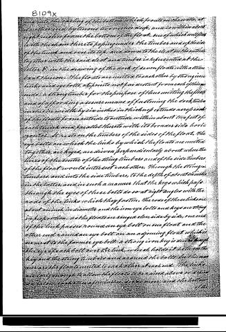
and into the endling of the bottom which fronts on the well, at its other end by two iron ties which are within about eight inches from the bottom of the floor, one of which will pass with the chain there to passing under the timber and up the side of the timber and over its top, and down to the cleat on the outside together with the said cleat and timber is represented at the letter D, in the drawing of the dock of seven floats with a steam boat thereon. The floats are united to each other by strong iron links and eye bolts, at points not far distant from each other, under a strong timber for the purpose of thus uniting the floats and of affording a secure means of fastening the dock, two inches in width by six inches in thickness extends across each of the floats from outside to outside within about two feet of each timber and parallel thereto with its broader side horizontal. It rests on the timbers of the sides of the float, the eye bolts on which the links by which the floats are united together, are keyed, are driven perpendicularly about where the lines of the centre of the string timbers and of the side timbers of the float would intersect each other, through the string timbers, and into the side timbers, to the depth of about six inches in the latter, and in such a manner that the keys which pass through the eyes of these bolts do so at right angles with the rods of the links which they fasten. The rods of these links are about an inch in diameter and the iron eye bolts and keys are strong in proportion. As the floats are ranged close side by side, one end of the link passes round an eye bolt on one float and the other end round an eye bolt on an adjoining float which is nearest to the former eye bolt, a strong iron key is driven through the eye of each bolt over the link, which holds it between the key and the string timbers and around the bolts. In this manner are the floats united to each other at each end. The links are long enough to allow the floats to be raised above or driven below each other for various purposes, and the bottom of the
Page 11.
of the links large enough and the keys high enough above the timbers to allow the links play for this purpose, and also for the purpose of permitting the floats to tap to and fro a few inches enlwise by each other. To allow the floats to play up and down by each other without straining the links, the ends of each string timber from the inner side of each eye bolt, have a gradual slope which diminishes their thickness at the ends of the timbers about two inches, and for the same purpose the links have an equal downward slope, from their centre towards their ends—except where the links are made long for the purpose of allowing the floats to be fastened to each other at the same distance apart from each other for the purpose of forming a dock, in which case the slope in the link should be diminished in a multiplied ratio to its increase in length. The cradle for steamboats is constructed to raise the keel of the boat about three feet above the deck of the dock. The lower timbers of the cradle are twelve inches in thickness by fourteen in width, and extend only from outside to outside of each float, and rest on the side timbers of the float, and are parallel to the string timbers. One of these lower timbers is placed on each side of the centre of each float, and about three feet from two other timbers eight feet long, twelve inches thick by fourteen wide, rest on these at right angles with them, one on near each side of each float. Keel chalks about eight inches square and three feet long rest on these lengthwise with them. The other lower timbers of the cradle are to support the bilge of the vessel and are of the same length and dimensions with the former and parallel thereto, and are about twelve feet from the centre of the float, one of them on each side of the centre. Timbers of the same dimensions with these, except that they are about two inches shorter, rest on these and lie lengthwise with them, and have their ends equally distant from the sides of the floats. On these again, rest bilge chalks eight inches square by three in length.
Page 12.
All the timbers of the cradle are movable, that the cradle may be adapted to the size of the vessel, and the distance at which the floats may be placed from each other, and have temporary fastenings. The timbers of the cradle which are twelve inches wide by fourteen thick, rest on their edges, having their broad sides perpendicular. The lower timbers of the cradle are only slightly spiked to the six timbers of the floats, and the other timbers of the cradle on each float are slightly spiked to each other and fastened by spikes to those lower timbers on which they rest. The whole of the timbers of the cradle are thus fastened so securely that they will preserve their position beneath the water when the dock shall be sunk for the purpose of floating the vessel over the cradle. The dock may be sunk for the purpose of receiving the vessel which is to be repaired on its cradle by being allowed to fill with water to such depth as shall become easy to sink her with convenience. The water is admitted into the dock for this purpose by holes about an inch and a half in diameter, made through the bottoms of the floats. These holes are only made in the pump wells, as a perpendicular line would describe the same upon the bottom of the floats, and only one hole is made in each pump well. Each of these holes is provided with a plug by which it may be stopped, and each plug has an eye bolt passing through its centre from end to end and strongly riveted at the lower end, having its eye at the upper end. A strong rod of iron with an eye at each end stands perpendicularly in each tank and extends from a horizontal lever of iron which is within about seven inches of the top of the tank which has an eye at that end to which the perpendicular rod is united. This perpendicular rod in each tank is united to the eye or bolt in the plug by the rod of the eye of the perpendicular rod passing through the eye of the eye bolt which is in the plug. The horizontal lever is united in the same manner to the upper end of the perpendicular rod. The horizontal lever is nearly parallel to
Page 13.
to the broader sides of the trunk and is about half an inch in thickness by an inch and a half in width, and plays upon a strong iron pivot as a fulcrum, at about eight inches from the eye of the perpendicular rod, by means of an eye made in the lever through which the pivot passes, which is so made as not to weaken the lever. These eyes are neatly made so that the plug may be drawn from and returned into the holes by the play which the rods may have, which pass through the eyes respectively, and so that the pressure upon the plug when a force is applied by means of the horizontal lever to return and hold it tight in its hole, shall be upon the center of the plug as nearly as may be. This fulcrum or pivot is horizontal and strongly driven into a piece of strong timber, which is strongly spiked on and to the interior of the trunk on that side of it which is towards the needle. By this lever the plug may be drawn so far as to admit the water as fast as it would enter through a hole an inch and a half in diameter, and returned again into the hole, and held or fastened in either position by means of a chain which is strongly attached to the end of the lever opposite to that which is connected to the perpendicular rod, and which may be fastened to a cleat, which is strongly spiked to one of the stanchions within the pump well, against which the end last mentioned of the horizontal lever is to play, and near the top of the well or to a pin driven horizontally in the stanchion at such point below the top of the well as that the end of the lever last mentioned being, or resting upon it, will hold the plug in the hole within the half of an inch of being drawn therefrom. The lever is to be drawn towards the cleat and fastened when it is to be held close in the hole, and to be fastened to the pin when the water is to be admitted into the dock. The lever is not to be allowed to pass below this pin, that the end of the lever towards the cleat may always be a certain means of stopping the hole, from which the pin is never to be
Page 14.
to be entirely drawn. The bottom of the floats where the holes pass through them, are made five inches thick by the addition of a plank at each hole three inches thick, and eight inches square fitted close and tight to the bottom of the float and strongly spiked thereto, through the entire of which the hole passes. Each hole on the interior of the bottom is nearly three inches in diameter. The plug of each hole, so far as it is intended to enter the hole, has somewhat the figure of a cone rounded that it may be easily drawn. It has also a horizontal shoulder which projects half an inch all around it, and fits to, and upon the bottom of the float, so as to make a tight joint between the shoulder and the bottom. The length of the plug below this shoulder is about four and a half inches in length. That part of the plug which passes into the hole, fits tight but easily in the hole, as a security against the plugs being disturbed when they should not be. They are not allowed to pass through the bottom of the floats, and the tops of the wells are each of them, provided with a hatch door, hung with hinges. To this door there is an also a lock, by means of all which the wells may be entirely closed and fastened at the top so as to prevent the plugs from being improperly disturbed. The lower ends of the pumps rest on the bottom of the floats. Their upper ends extend to within about a foot and a half of the tops of the trenches. The pumps are about twelve inches in diameter; their bore is about four inches in diameter. Their spears are of iron and measure an inch in diameter, and extend about four feet six inches above the tops of the trenches. In each pump well, the pumps are from centre to centre about three feet from each other. The water is discharged from them through the sides of the trench on the deck of the dock by tubes, which lead from the pumps at about a foot and two inches below the tops of the trenches. The pumps are nearly perpendicular, they have a slight inclination at the top towards that end of the float at which they are respectively
Page 15.
respectively placed. Something more than one half of the top of each pump well is covered with a door as mentioned, and the residue of the top, with a hatch door through which the spears of the pumps pass. The upper ends of the pumps are fastened to the stanchions within the wells on that side of the tanks towards which their upper ends incline, which pumps are represented in the drawing marked B. of the profile of a float, and also in the drawing C. B. D. of the dock of seven floors at the letter D, except that the upper ends of the pumps in these drawings, improperly appear above the tops of the tanks. The pumps in each well are both worked at the same time by the same pendulum brake and by the same person. The horizontal or roof lever which is connected with both spears of the pump of each well, is about four feet six inches above the tops of the tanks, where it plays on a horizontal pivot or fulcrum which has its feet on the hatch floor at the top of the pump well, to which floor its feet are strongly fastened—which horizontal lever, pendulum brake and fulcrum as they are connected with the spears of the pumps and the hatch floor of the pump well, are represented in the drawing last referred to at the letter D. A horizontal platform or floor about sixteen inches wide and twelve feet in length on the outside of each tank over the end timbers of the float, is fastened securely to each tank about two feet below its top by spikes and supported at each end by strong timbers three inches thick by five in width, the lower ends of which are let about four inches into the end timbers of the floats at about midway of these timbers from each of their ends, which supporting timbers are strongly spiked to those end timbers and to the side of the tank to which they form braces, as well as a support to the platform. This platform is constructed for those to stand or walk upon who may be employed in sinking or raising the dock. The dock may
Page 16.
may or may not require ballast to sink it, according to the weight of the materials of which it is made. If these be much lighter than the water in which it is to be sunk, ballast will be necessary, and the weight of ballast which will be necessary will be in proportion to the leviety of the materials, in comparison with the water. As the dock shall become saturated with water by use, the weight of ballast necessary will be diminished. When water has been admitted into the dock until its chambers have been nearly or quite filled, if it shall appear by the buoyancy of the dock that ballast will be necessary to sink it, this ballast may be then placed in the deck of the dock, the quantity of which will be regulated by the relative surfaces of the water within and without the dock, ballast should be added until the surface of the water within the dock is lower than the surface of the water in which the dock floats. The ballast should be placed near the tanks and be so distributed upon the dock as to preserve its deck as nearly horizontal as may be. Previous to the application of ballast, the holes through which the water is admitted are to be closed. When sufficient weight of ballast has been placed on the dock, to sink it to the depth required, by merely letting in an additional quantity of water, the holes are opened to let in this water. As the water is admitted, the dock will sink in the water about as fast as the water shall rise in the chambers while those shall be filling, and then more suddenly to about that further distance or depth, which will make the tanks between that point up to which the water has risen in the tanks, and that to which the tanks must sink to displace a weight of water equal to that weight which is at that point of time sinking the dock and afterwards again about as fast as the water will rise in the tanks, as the same shall be permitted to enter for this purpose through the holes and elsewhere. When the dock by this slow process of filling first its chambers and afterwards its tanks as far as these shall be allowed to fill, shall have gradually sunk with its deck sufficiently beneath the surface.
Page 17.
surface of the water to allow the vessel which is to be raised upon it to be floated over the middle of the dock, the holes are to be stopped with the plugs, which have been described by means of the levers and fastenings described, as prepared for this purpose by which the dock will be suspended, at, and will remain at about that precise depth to which it has been thus sunk beneath the surface of the water, when the surface of the water within the tanks is lower than the surface of the water in which the tanks float, it will then be that the weight which sinks the dock is sufficient to hold her down as low as she is thus sunk, under the circumstances of the unequal surfaces of water within and without the dock. The tops of the tanks should not be allowed to sink so near towards the surface of the water by the sinking of the dock beneath its surface, that there will not still be a reserved capacity in the tanks or that portion of them which remains above the surface of the water in which they float, as will secure them against the danger of being sunk by the waters entering them either by the holes in their sides, through which the water is to be discharged from the pumps, or by their upper ends or tops. This reserved capacity will be in proportion to the additional weight of water which the tanks would still displace by the docks sinking deeper before the water would be admitted into them by the holes in their sides which have been mentioned which are about a foot and nine inches below their tops, or in the event of these holes being closed, by the additional weight of water then the docks would displace before the water would enter them at their tops by the docks sinking deeper. A button marked with feet and inches of the length of the tank is nailed perpendicularly on the outside of each tank, as well as on the inside of each pump well, by which the depth of the dock beneath the surface of the water may be readily seen and also the relative surfaces of the water on the interior and exterior of the dock and tanks. The lower end of the bottom in the interior of the tank
Page 18.
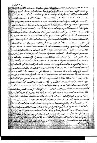
tanks with a view to the object last mentioned extends a few inches below the lower end of the tank and a corresponding mark on the interior of the end of the float. When the dock has been sunk to the point mentioned it may be sunk lower by letting in more water, or raised by pumping water from its chambers. The dock may also be suspended by means of the well floats in the tanks, with her deck at any depth beneath the surface of the water which may be required by making fast the chains which are attached to the lower ends of the well floats, to the cleats on the outside of the tanks leaving but such length of chain between the cleats and the eye bolts of the well floats as will cause the weight which is to sink the dock to be borne entirely by these floats when the dock shall have sunk to the required depth and thus prevent the dock from being sunk lower by such weight. So it may be allowed to sink gradually by means of the well floats by making the chain so short between the cleats to which they are fastened, and the eye bolts of the well floats, as will suspend the weight which would sink the dock to these floats, before the dock's deck has sunk beneath the surface of the water, and then slackening off gradually and little by little the chains from the cleats until the dock shall have gone down to the required depth. The chains may then be slackened off from the cleats with or without the aid of a windlass which turns on the six inch timbers of each tank near its top and projects horizontally from it about four inches around which horizontal projection, the chain of each well float is wound two or three times between the points at which it passes over the top of the tank and that at which it is fastened to the cleat according to the first described mode of suspending the dock with its deck beneath the water at any depth required by means of the well floats, the holes in the bottoms of the floats should be closed after the chambers of the dock have been permitted to fill or nearly to fill with water until the ballast which is necessary to sink the dock shall have been placed upon it and then drawn accordingly.
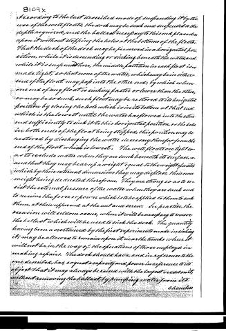
Page 19.
According to the last described mode of suspending it by the use of the well floats, the dock may be sunk and suspended to the depth required, and the ballast necessary to this end placed upon it without stopping the holes at the bottoms of the floats. That the deck of the dock may be preserved in a horizontal position, while it is descending or sinking beneath the water, and while it is suspended there, the middle partition in each float is made tight, so that none of the water, which may be in either end of the float may pass into the other end; by which when one end of any float is sinking faster or lower than the other, or may be so sunk, such float may be restored to its horizontal position by closing the hole which is in its bottom at that end which is the lowest until the water has flowed into the other end sufficiently to sink it to this horizontal position, or the holes in both ends of the float being stopped, this position may be restored by discharging the water necessary therefor from the end of the float which is lowest. The well floats are tight so as to exclude water when they are sunk beneath its surface, and that they may bear up a weight equal to the weight of water which by their external dimensions they may displace, their own weight being deducted therefrom. They are strong so as to resist the external pressure of the water when they are sunk and to receive the force or power which is to be applied to them to sink them, at their upper end at the nut and screw. In practice, the suction will seldom occur, when it will be necessary to remove the ballast which will be used to sink the dock. The quantity having been ascertained by the first experiments made in sinking it, may be allowed to remain upon it, near the tanks where it will not be in the way of the operations of those employed in making repairs. The dock should have, and in reference to the one described, has, so great a capacity and power in reference to its object that it may always be raised with the largest vessel in it, without removing the ballast by pumping water from it.
Page 20.
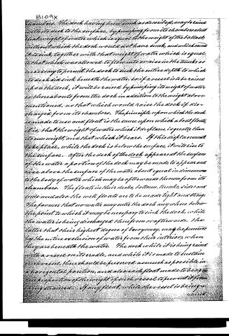
8109x
chamber. The dock having been sunk as described, may be raised with its deck to the surface, by pumping from its chambers about that weight of water which is equal to the weight of the ballast without which the dock would not have sunk, and which can be let in, together with that weight of water which is equal to that which was allowed to flow into or rise in the tanks as necessary to permit the dock to sink the entire depth to which its deck did sink beneath the water. So if a vessel is to be raised upon the dock, it will be raised by pumping its weight of water or those abouts from the dock in addition to the weight above mentioned, as that which would raise the dock if discharged from its chambers. The principle upon which the dock is made to use and float is the same upon which a boat floats; it is, that the weight of water which it displaces, is greater than its own weight, and that which it bears. If this displacement take place, while the dock is below the surface, it will rise to the surface. After the deck of the dock appears at the surface of the water a portion of the dock may be made to appear and rise above the surface of the water about equal in dimension to the body of water which may be afterwards thrown from its chambers. The floats in their decks, bottoms, tanks, sides and ends and also the well floats are to be made tight and strong. The former that no water may enter the dock anywhere below the point to which it may be necessary to sink the dock, while the water is being discharged therefrom or afterwards. The latter that their highest degree of buoyancy may be preserved by the entire exclusion of water from their interior, when they are beneath the water. The dock while it is being raised with a vessel on its erable, and while it is made to sustain such vessel, there should be preserved as much as possible in a horizontal position, and also each float made to bear its due proportion of the weight of such vessel to prevent it from being strained. If any float, while the vessel is being raised
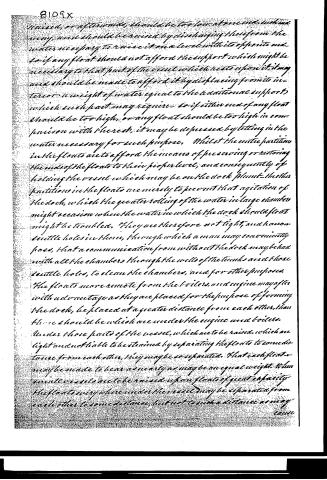
Page 21.
raised, or afterwards, should be too low at one end, in some way, and should be raised by discharging therefrom the water necessary to raise it on a level with its opposite end. So if any float should not afford the support which might be necessary to that part of the vessel which rests upon it, it may and should be made to afford it by displacing from its interior a weight of water equal to the additional support which such part may require. So if either end of any float should be too high, or any float should be too high in comparison with the rest, it may be depressed by letting in the water necessary for such purpose. Whilst the centre partitions in the floats are to afford the means of preserving or restoring the ends of the floats to their proper level, and consequently of holding the vessel which may be on the dock plumb, the other partitions in the floats are merely to prevent that agitation of the dock, which the greater rolling of the water in large chambers might occasion when the water in which the dock should float might be troubled. They are therefore not tight, and have small scuttle holes in them, through which a man may conveniently pass, that a communication from without the dock may be had with all the chambers through the wells of the tanks and those scuttle holes, to clean the chambers, and for other purposes.
The floats more remote from the boilers and engine may after with advantage as they are placed for the purpose of forming the dock, be placed at a greater distance from each other, than those should be which are under the engine and boilers.
Under those parts of the vessel, which are to be raised, which are light and not liable to be strained by separating the floats to some distance from each other, they may be so separated. That each float may be made to bear as nearly as may be an equal weight. When small vessels are to be raised upon floats of great capacity the floats everywhere under the vessel may be separated from each other to some distance, but not to such a distance as may cause
Page 22.
since the vessel to be strained. Links suitable in their lengths for connecting the floats from one to the other should be prepared and each should belong to the dock. The timbers of the dock should be so arranged as to hold the vessel plumb which is raised thereon, and to offer it every where the requisite support. Each float has on one of its sides two strong iron eye bolts that is to say, one eyebolt in each string timber, driven securely through this timber and into the side timbers of the floats, with a strong iron ring in the eye thereof, by which the dock and each float thereof when detached may be made fast to the shore or other object. All the floats of the dock which have been described are in all respects similar to each other, and all that appertains to any one of them, appertains in the same manner to each of the others. As the downward pressure upon the dock in raising a vessel will be great, the bottom of the floats should be strong. The pressure upon the well floats will be at the nut and screws. They should be made capable of receiving the force which is to sink them at this point. The floating dry dock for repairing steam boats and other vessels, used and known before the said improvements thereon made by the inventor of the said Thomas, may be described as an open boat generally made much after the fashion of a common scow, large enough to receive the vessel into it which is to be repaired. It is so constructed that one of its sides or ends may be opened for the purpose of admitting such vessel, and closed after the vessel shall have been so admitted. When it is used to raise a vessel, it is sunk deep enough in the water to allow the vessel to be floated into it through the opening which may be made in the end or side as mentioned, which having been done and the opening closed up the water is closed within it, and which was admitted therein for the purpose of sinking it and also of floating the vessel into it, is then drawn out of it by the use of pumps. The vessel which at first floated within the dock, during this process of removing the
Page 23.
the water, gradually lowers and rests upon the cauldle prepared for it. After the water has been thrown out of the dock, the vessel is in a situation in which it may be repaired. While the dock has thus to be sunk deep enough to allow the vessel to be floated into it and over the cauldle herein prepared, it is not allowed to sink so low that its sides or ends, or either of them shall be entirely below the surface of the water, inasmuch as this would prevent the water which is in the dock from being displaced by the use of the pumps. This dock is not provided with the means of being suspended at any particular depth of water which would place it between those points at which the vessel might be floated into it and the water pumped out of it. When the water is admitted into it to sink it for the purpose of admitting into it the vessel which is to be raised, and when it is sunk for this purpose the weight which will thus sink it, or may be used thus to sink it would probably sink it below the depth from which the water could be thrown out of it by the use of pumps should the water be deep enough to allow it so to sink. It is therefore only used in water where there is a bottom or foundation, or resting place, by which it is prevented from sinking to a depth at which its sides would be entirely below the surface of the water. During the process of removing the water from within the dock, it rises from its foundation or resting place and floats the weight of water which has been pumped from the dock to raise it, is great in comparison with the weight of the vessel which is to be raised within it, and must probably exceed this weight in all cases even greatly beyond the amount of that weight of water, which would be below the level of the bottom of the vessel and floated over the cauldle, and which would have to be pumped out to get into the vessel to repair it. The sides of the dock are necessarily high, to afford the water in which the vessel may be floated over the cauldle, and consequently excludes much of that light which it would be desirable for the workmen to have while repairing
Page 24.
repairing the bottom of the vessel, and prevent the circulation of air which would be useful to dry it for the purpose of making those repairs. The workman in making them will also find themselves below the surface of the water in which the dock floats, exposed to the damp and inconvenience occasioned by leaks in the dock. Leaks generally considerable from the circumstance that the dock has to be opened by a sort of gate or door which cannot be easily closed tight, or enough entirely to exclude the water, and also from the circumstance that the dock, as well from being large as in consequence of the nature of its construction being such as to be opened for the purpose mentioned is comparatively weak. It has no deck on or above which the vessel may be raised, no chambers from which the water may be discharged from below the vessel which is to be raised by which to elevate it above the surface of the water in which the dock floats, nor tanks, nor well floats by which to suspend the dock, nor any deck or chambers of any kind, nor partition or partitions to separate the water within the dock by which it may be kept level, or the vessel therein plumb while it is being raised, or afterwards, by discharging more water from that side or part of the dock which should be raised for the purpose of preserving it level or restoring it to that position. The said new and useful improvements invented by the said Thomas on the floating dry dock which has been herein last before described will be now designated as they constitute a part of the improved floating dry dock for repairing steam boats and other vessels, which has been herein before described, and the said improvements more particularly denoted, and their principles more particularly illustrated. For which purpose reference will be made to the improved dock of nine floats which has been herein before described, and to the several improvements herein mounted by the said Thomas, which improvements, are
Page 25.
8109x
1st. The partitions in the said improved dock which separate into the interior of each float of the dock into several chambers, by which it may be balanced and preserved in a position sufficiently horizontal by pumping water from one of its ends, or letting it in at the other. It is not improbable that the partition which in the dock of nine floats is represented to be tight, should be so much higher as the dock or connect closely with it in as much as no great inequality in the height of the mass of the floats, in the process of raising the dock will take place until after the water which was within the floats has been considerably discharged, and when it will be any where near the middle of the float, much below the deck; nor are the other two partitions greatly important, since the earlings would perform much of what is the object for which these partitions are made.
2d. The deck of the improved dock, for the purpose of raising the vessel thereon, which is to be repaired, and of raising it above the surface of the water and of affording to the workmen, a dry floor to work upon. Also for the purpose which it forms of more conveniently giving that strength to the dock which is necessary to preserve it from leaking—and likewise for the purpose of forming more conveniently the chambers which are beneath the deck, as well as for the further purposes herein after mentioned.
3d. The chambers beneath the deck of the improved dock for the purpose of admitting water therein when the dock is to be sunk; also for the purpose of raising the dock by pumping the water therefrom, after the holes shall have been stopped by which the water had been admitted into the dock and so because of these chambers or a chamber in conjunction with the tanks described and substituted for the walls or sides of the dock, the water to be pumped from the dock, to raise it is, relatively to the weight to be raised, greatly diminished and consequently, the dock is hereby rendered stronger and lighter.
Lilly
Page 26.
leaky. 112. The tanks of the improved dock, are a substitute for the sides and under-walls of the floating dry dock, the tops of which tanks are like the sides and ends of the said floating dry dock, to remain above the water, to preserve the means of raising the dock by pumping the water from its chambers or chambers and as a substitute preferable to the sides or walls of the floating dry dock. Because by such substitute, in conjunction with the chambers mentioned, the dock is raised by pumping from the chambers, in addition to the water, which is in the tanks a weight of water about equal to the weight of the vessel which is to be raised, added to that weight by which the dock was sunk to the depth from which it is to be raised, a weight of water, relatively to the weight to be raised greatly less than that which has to be pumped from the floating dry dock before known, relatively to the weight to be raised in it, and because by the substitute, the vessel which is to be raised above the surface of the water in which the dock floats, and of a space allowed between the several tanks, each side of the dock, that air may freely circulate about the vessel to dry it, and light be fully admitted to it, by which to repair it; and also that the ends of the dock may be allowed to be open for those purposes (see the tanks, letter B, in the drawing before referred to, profile of a dock of iron floats, and space between these tanks—see also the drawing B, a side view of a float with the midship of a steam boat thereon, letter C, which will show the end of the dock in the manner in which both its ends are to be open). This substitute of tanks for the sides of the dock is preferable also, because by it the dock will, when sunk, prevent its surface to be acted upon by the current, and because by it the dock may be composed of many floats, and because the tanks, while they are a substitute for the sides of the floating dry dock, and secure as fully as sides could do, the means of raising the dock by pumping water therefrom, afford also the means of suspending the dock in a horizontal position.
Page 27.
in the water at any depth desired by the water which they displace or may be made to displace; and afford likewise a convenient place for using and protecting the well floats, constructed for the same purpose of suspending the dock at any depth beneath the water by the water in which these may be made to displace; and afford also a convenient place within which the pumps may be protected and conveniently used.
5th. The formation of the improved dock out of several distinct floats together, by which it is more easily & cheaply constructed, is stronger in the construction, is more manageable, more convenient for use, by which the power necessary to raise any particular vessel, whether large or small may be employed, and no more, by using that number of floats which will give this power, and detaching the sweep if convenience require it, by which also the dock itself may be easily repaired, by using some of the floats as a dock to raise others of them to repair them, and by which the dock by detaching the floats or separating them, may be removed into narrow inlets of the shores, or made to occupy a narrow space at the shore to secure it against accidents or the floating ice or drifts, and by which the floats or any number of them when not required to be used as a dock, may be applied usefully to various other purposes which said improved dock however may upon, and in conformity with, the principles of the said inventions or some or many of them be formed of one float only or of one or more floats with the addition of all or any of the other inventions of the said Thomas which have been herein enumerated and described or which may be hereinafter described or enumerated as the inventions of the said Thomas. By composing the dock of several floats, the ends of the ends may be more easily removed,
Page 28.
8109x
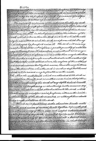
which may be removed for the purpose of repairing every part of the vessel, inasmuch as one end of each float may be disposed by itself by means of wedges or otherwise to allow of such removal.
The capacity or power of the improved floating dry dock will be nearly in proportion to the surface of water which it may contain in its chamber, or chambers if there be more than one, that is, in that space within the interior of the dock, which is lower than the deck and into which the water may be admitted to sink the dock, and from which it may be discharged by pumps to raise it. The dock will raise any vessel which does not displace a greater quantity of water than may be thrown from its chambers, and will not raise any vessel that does displace more water than may be thrown.
The tanks and pumps must extend above the malle so high that their tops will extend above the surface of the water and and in such manner that by their means, the water may be thrown from the chambers, when the dock is sunk so deep that the vessel which is to be raised may be floated over the malle.
6th. Also the well floats which are attached to the dock as an addition thereto, and as another mode beside that of the tanks of suspending the dock at any depth desired beneath the water by lengthening or shortening in the manner described, the chain which attaches them to the dock, which floats may be used for said purpose, either on the inside or the outside of the tanks described, or although there should be no tanks whatever to the dock.
Which said partitions, decks, chambers, tanks, wells, floats, and union of several floats together, to form the dock are all and every of them new, and useful improvements on the floating dry dock, invented by the said Thomas for all and every of which he solicits a Patent according to the laws of the United States in that behalf.
made
Page 29.
made and provided. Done at the City of St. Louis on the 20th of July, A.D. 1834.
Witnesses:
Wilson Primm.
W. R. Gimsley.
John Thomas
Patented March 26, 1834
Drawing
Published accounts: journal notice
Notice in the monthly list of patents (listed with a different spelling or date)
Journal of the Franklin Institute, new ser., vol. 14 (1834), p. 252 · View the page
For an improved Floating Dry Dock, invented by John Thomas, of the city of St. Louis, Missouri, and assigned by him to James H. Peck and others, to whom the patent has issued; March 26.
About this record
- Patentee
- DATAMP
- Date
- the Name and Date index of patents, DATAMP, USPTO records
- Invention
- DATAMP
- Listed in
- the Name and Date index of patents, DATAMP, USPTO records, Jim Shaw's X-patent list, the Journal of the Franklin Institute, Journal, Burke's List of Patents (1847)
- The sources give the patentee's name differently; the name shown follows DATAMP and Shaw.
- Also listed in a contemporary journal or list under a different spelling or date; the record shown follows the standard lists.
- Burke's 1847 Patent Office list gives the same patent.