

Drawings and documents
USPTO scan
The patent as scanned by the USPTO
-
 Page 1
-
 Page 2
-
 Page 3
-
 Page 4
-
 Page 5
-
 Page 6
-
 Page 7
-
 Page 8
-
 Page 9
-
 Page 10
-
 Page 11
-
 Page 12
-
 Page 13
-
 Page 14
-
 Page 15
-
 Page 16
-
 Page 17


U.S. Patent and Trademark Office · Google Patents
Show the transcription Hide (6,557 words)
Machine transcription (LightOnOCR) of the pages as scanned by the USPTO, most of them the handwritten copies made when the records were restored after the 1836 fire. Not checked; it can misread handwriting, so compare it with the scan.
Page 2.
United States Patent
Patent No.: X2954
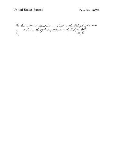
For Gideon Davis Specification. Suppl. in the Plough, Patented to him on the 27th May 1818. See Vol. 5, page 1461. (1818)
Page 3.
United States Patent
Patent No.: X2954
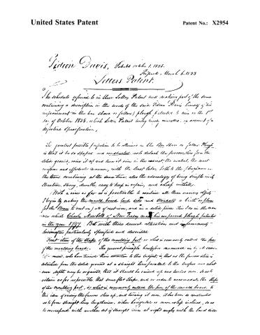
Victor Davis, Patent October 1, 1825.
Reissued, March 6, 1833
Letters Patent.
The schedule referred to in these Letters Patent and making part of the same containing a description in the words of the said Victor Davis himself of his improvement in the bar share or follow plough patented to him on the 1st day of October 1825, which Letter Patent being hereby cancelled, in account of a defective Specification,
The greatest possible perfection to be attained in the Bar Share or Follow Plough is that it be so shaped and constructed, so to detach the furrow slice from the solid ground, raise it up and turn it over in the easiest, the most uniform and effective manner, with the least labor, both to the ploughman and the team, combining at the same time, also the advantage of being simple in its structure, strong, durable, easy to keep in repair, and cheap in its cost.
With a view as far as is practicable to combine all these various objects, I begin by making the mould-board (and side and standard or birth or place for the Beam to rest on) all of cast iron, and in a solid piece. This I do in the manner which Charles Newbold of New Jersey made his improved plough patented in the year 1797. But with these several alterations and improvements hereinafter particularly specified and described.
First item of the shape of the moulding part or what is commonly called the face of the moulding board. The general principle heretofore canvassed in by so several of our men, who have turned their attention to this subject, is, that as the furrow slice is detached from the solid ground at a straight line parallel to the surface and whatever depth may be required, that it should be raised up and turned over, so as to retain as far as possible that same flat shape, and in order to accommodate the shape of the moulding part, or what is commonly called the face of the mould board, to this idea of raising the furrow slice up, and turning it over, it has been so constructed as to form straight lines lengthwise, either horizontal or more or less inclined, so as to correspond with another set of straight lines at right angles with the last lines.
Page 4.
United States Patent
Patent No.: X2954
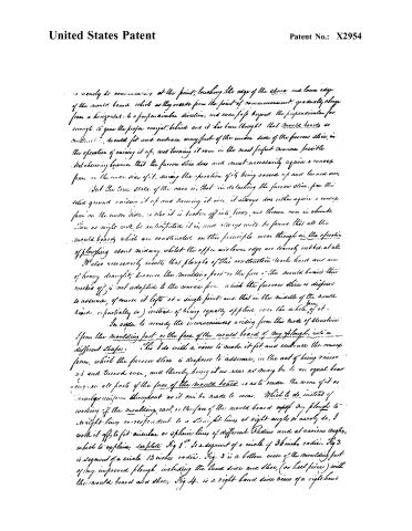
I nearly do commencing at the point, touching the edge of the share and lower edge of the mould board which as they proceed from the point of commencement, gradually change from a horizontal to a perpendicular direction, and even go beyond the perpendicular far enough to give the proper overjet behind and it has been thought that mould boards so constructed, would fit and embrace every part of the under side of the furrow slice, in the operation of raising it up, and turning it over in the most perfect manner possible. Not observing however that the furrow slice does not necessarily acquire a convex form on the under side of it, during the operation of it being raised up and turned over.
But the true state of the case is, that in detaching the furrow slice from the solid ground raising it up and turning it over, it always does either acquire a convex form on the under side, or else it is broken off into pieces, and thrown over in shreds.
This as might well be anticipated it is, and always will be found, that all the mould boards which are constructed on this principle wear through in the operation of ploughing about midway, whilst the upper and lower edges are scarcely rubbed at all.
It also necessarily results that ploughs of this construction work hard and are of heavy draught, because the moulding part or the face of the mould board thus worked off is not adapted to the convex form which the furrow slice is disposed to assume, of course it lifts at a single point, and that in the middle of the mould board (or partially so) instead of being equally applied over the whole of it.
In order to remedy the inconveniences arising from this mode of structure I form the moulding part or the face of the mould board of my plough, into a different shape. This I do with a view to make it fit and embrace the convex form, which the furrow slice is disposed to assume, in the act of being raised up and turned over, and thereby bring it as near as may be to an equal bearing on all parts of the face of the mould board so as to render the wear of it as nearly uniform throughout as it can be made to wear. Which to do instead of working off the moulding part or the face of the mould board of my plough to straight lines corresponding to a straight line at right angles or nearly so, I work it off to fit circular or spheric lines of different radius and at various angles, which to explain see plate Fig 1. Is a segment of a circle of 36 inches radius. Fig 2 is segment of a circle 12 inches radius. Fig. 3 is a bottom view of the moulding part of my improved plough including the land side and shoe (or heel piece) with the mould board and shoe. Fig 4. is a right hand side view of a right hand
Page 5.
United States Patent
Patent No.: X2954
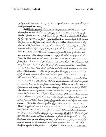
plough with a cast-iron share, Fig 5 is a left-hand view of a right-hand plough with a wrought-iron share.
To shape the moulding part or make the face of the mould board sufficient, it to be for a 10 inch (or a two horse) plough, such as would be a suitable size for turning a furrow slice of about 12 inches, having obtained a suitable block, I begin by laying off the bottom, see fig. 3. I consider 24 inches a suitable length for the land side, say from (a,) at the point to b, at the heel of the plough; it may be more or less; from (a,) at the point I draw a circular line, with the large segment fig. 1, so as to intersect a line at right angles to the plane of the land side at b, 1 and 12 inches distant, with the arc of the circle extended out from the plane of the land side; see a, a, a, a. Then having worked the edge of the block nicely off to this line, I turn the block down on this bottom, and then work the side from (a,) at the point (fig. 4, to a,) at a perpendicular raised 12 inches from the horizon or bottom) and 24 inches back from the point of commencement, and vertical to the circular bottom line at that point with the arc of the circle extended in towards the plane of the land side. Then having wrought to the shape of this circular line, I apply the small segment fig. 2, with the arc of the circle extended in towards the aforesaid two lines, and as near at right angles with them as is practicable, and then I work off the face of the block so, that this small segment will touch the aforesaid two circular lines, at various places, corresponding to lines (c, c, c, c, &c.) and so as to produce as near as may be an equal bearing on all parts of the face of the block. These lines at (c c c &c.) if extended would at terminate at a point at (d) which is about 24 inches below the horizontal line (or bottom) of the mould board and vertical to heel or end of the land side. This done forms a shape which so far as appears has not before been applied to any solid, that is, not before used, or ever known. But which however, of these shapes, that are known and used, it is thought to approach nearest to those of the reproduce or spiral curve but it is not exactly either, neither can I find a name that would properly embrace this shape, save it is, (moulding form for reversing the soil.) But it is a fact that this shape when applied to practice, is found in the operation of raising the furrow slice up and turning it over, to fit the convex form, which it is disposed to assume on the under side much more uniformly, than any other shape heretofore applied to that purpose. The proof is, that mould boards of this shape
Page 6.
United States Patent
Patent No.: X2954
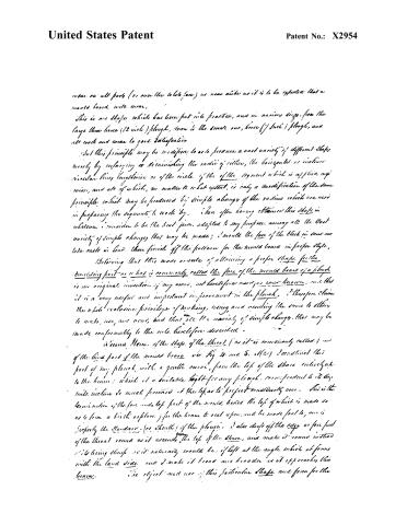
wear on all parts (or over the whole face) as near alike as it is to be expected that a mould board will wear.
This is one shape which has been put into practice, and in various sizes, from the large three horse (12 inch) plough, down to the small one, horse (7 inch) plough, and all work and wear to good satisfaction.
But this principle may be modified to so to produce a vast variety of different shapes merely by enlarging or diminishing the radius of either, the horizontal or inclined circular lines, likewise or of the circle of the of the segment which is applied respectively, and all of which, no matter to what extent, is only a modification of the same principle which may be produced by simple change of the radius which are used in preparing the segments to work by. Then after having obtained this shape in whatever I consider to be the best form, adapted to my purposes, among all the vast variety of simple changes that may be made; I mould the face of the block in such as take casts in lead, then finish off the pattern for the mould board in proper style.
Believing that this mode or mode of obtaining a proper shape for the moulding part—or what is commonly called the face of the mould board of a plough—is my original invention, if my own, not heretofore used, or ever known, and that it is a very useful and important improvement in the plough, I therefore claim the whole exclusive privilege of making, using and vending the same to others to make, use, and vend, but that all the variety of simple changes that may be made conformably to the rule heretofore described.
I claim Also, of the shape of the throat (as it is commonly called) and of the hind part of the mould board (as Fig 4 and 5, etc.) I construct this part of my plough, with a gentle curve, from the top of the share, which is to the beam; which is a suitable height for any plough, corresponding to its type, while incline to much forward at the top, as to project considerably over. This is the termination of the fore and top part of the mould board, the top of which is made so as to form a birth or place for the beam to rest upon, and be made fast to, and is properly the standard (or sheath) of the plough. I also drop off the edge or fore part of the throat round as it ascends the top of the share, and make it round instead of its being sharp as it naturally would be, if left at the angle which it forms with the land side, and I make it broad and broader as it approaches the beam.
The object and use of this particular shape and form for the
Page 7.
United States Patent
Patent No.: X2954
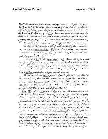
throat of the plough is to prevent brambles, long grass, weeds, or trash of any kind from
lapping to short on the throat, as they would do, if it was sharp, consequently prevent
it from hanging & dragging with the plough, as it otherwise would do, and the inclination
to forward at the upper part of the throat, forms a curve with the under side of the
beam so as to prevent any thing from becoming jammed, under the beam in
ploughing because the pressure from below naturally forces the incumbrance up,
then it works forward, and of course it falls off, and the plough runs clear.
The effect is; that in using a plough with the throat of this construction,
and without a swivel or cutter the seldom if ever a hook, this I consider
an improvement of great value in ploughing in (or among) clover, any tall grass,
weeds, long manure &c.
The hind part of the mould board. See (f) fig. 4. It drops off in a gentle
curve from the hind end of the wing of the share, up to the hind corner of the mould
board. This shape answers every purpose in turning over the furrow slice, and
as it does not come down to the bottom of the furrow; the plough works easier
to the ploughman, is lighter, cheaper, and handiomer,
Believing that the shape for the throat (or fore part) and hind part
of the mould board, have not been known or used before I applied them to
use, and that they are valuable improvements in the construction and use
of the plough I therefore claim the whole, and exclusive right of the use
and control of them to use; and vend to others, &c.
Third Item, of the structure of the land side and the connection of it with
the mould board and of the standard or fore and top part of the mould board.
In the construction of the plough Charles a Newbold aforesaid, in his improvement
made the land side and mould board in a solid piece. His land
side was nearly square, and made stout in order to give it strength I make
the land side of my plough thin and broad (see fig. 3 and 5, which shape
gives more strength vertically and without so much weight. This form of structure
makes it a guard also which prevents sods and dirt from working and clogging
that part of the plough. In order then to give the necessary strength side,
wise, I make a rib on the land side about midway between the top and
bottom of it see (h) fig. 3. This rib I make broad where it joins the
mould board at (h) and tapering as it extends back, towards the end of the
Page 8.
United States Patent
Patent No.: X2954
land side where there is a birth for the handle of the plough to be fastened on at (in) Fig. 3. and (in) Fig. 5, where I make a projection (or jog) which however cannot be represented in this drawing, to rise about half an inch for the end of the handle to rest against. This rest (or jog) contains the pressure of the handle andwise, so that the screw bolt is only required to confine it laterwise.
Charles A. Newbold, aforesaid, in the construction of his improved plough made the standards (or fore and lof part of the mould board) to pass up through a mortice in the beam. In my plough I make the standards (for fore and lof part of the mould board) to extend only up to the beam, the lof of it I make broad and flat, so that the beam may rest solid on it, and be fastened to it with a thumb screw bolt, which may be made either to pass up through the lof of the standard vertically at (j) Fig. 5, or it may pass down through the beam and the standard in an inclined direction, having on the inside of it a birth for the nut of the screw to work on at (j) Fig. 4. My object in using this mode of connecting the standards and the beam together, is, that of adjusting the plough, that is, that this, which I term the beam bolt, I use also as a swivel on which to turn the beam to the right or left, by the operation of which, the plough may be made to move or left hand.
There has been heretofore land sides constructed which were made broad and thin, but supported in a different manner. My improvement therefore consists only in my mode of making and applying the rib and the advantage of this particular mode, which is, that a rib thus made and applied give ample support to the land side in every way, and is at the same time entirely out of the way in ploughing so that clog does not go which sometimes goes in between the land side and the mould board, and clog up that part of the plough to through, and are not as we in the way, the peculiar shape in which I make the mould board of my plough, and of bringing the forepart of it (or rather) the standard up to the beam naturally causes it to extend further forward under the beam, than the standards, of any other construction of the plough does that I have seen, and which is quite an improvement because it equalizes the bearing of it the effect is that a smaller piece of timber will make the beam, than would if the standards and fastening to the handle were made nearer together, and of course the plough is lighter.
What I claim as my own invention and improvement in this claim is the
Page 9.
United States Patent
Patent No.: X2954
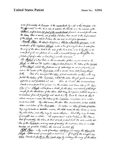
mode of connecting the land side to the mould board by a rib as here described, with (the projection) on the land side to sustain the handle, and the extension of the standard, or fore and top part of the mould board, forward, so much further under the beam than is usual; all of which I believe had much to the improvement of the plough, and which I claim the use and control of as aforesaid.
Fourth Item. the shoe (or heel piece) Charles Newbold aforesaid in the construction of his improved plough, made a bar of wrought iron to extend from the wing of the share, back to the end of the land side, and to lay flat on the under part of it; and fastened it on with a screw bolt passing up through this bar (which is properly a shoe or heel piece) and the land side.
The Stephens of New York, in the construction of their improvements on the plough in 1820 and '21 applied a shoe (or heel piece) on the bottom of the land side of their plough, which they fastened on by extending an ear (or projection) up and on the inside of the land side, with a small screw bolt passing through both.
Now it is manifest that shoes of such construction as these, with only protect the bottom of the land side, whilst the side, though quite as much exposed is not protected at all.
To obviate this inconvenience I make a countersink (or groove) on the outside and lower edge of the land side of my plough, which forms a birth, for the shoe, and admits of thickness enough for the substance of the shoe, that may be required, without any inconvenience from its projecting out—see k. k.) Fig. 3 and 5. I make the shoe to extend round, and under the bottom of the land side, and fasten it on with a small screw bolt. By which means the shoe thus constructed protects both the sides and bottom of the land side. In making my shoe if made of cast iron they may be made in cast-iron moulds, the chill makes the shoe harder, of course they wear better, and they may be made cheaper. But they may be made of wrought iron or steel. The improvement which I claim in this Item, is, that of constructing the shoe, so that it will protect both the side and the bottom of the land side, and my mode of making the cast-iron shoe, in imitation moulds all of which I claim the use and control of.
Fifth Item. a new mode of making, applying, and using the share of the plough whether made of wrought or cast iron. If I apply the wrought iron share I make it partly in the usual way by welding the wing of the share
Page 10.
United States Patent
Patent No.: X2954
on a landside see fig. 6. but I make the bar to extend back of the wing some two or three inches, as at (m) and fasten it to the cast iron part of the landside with a small screw bolt at (n) fig. 5. I then fasten the wing of the share to the mouldboard, with a strong screw bolt, having the head of it made to fit a tapering hole in the mould board, and passing down through the wing of the share at (p.) fig. 6. and drawn tight with a nut. If it be a right hand plough, this should be a left hand screw, and if a left hand plough then it should be a right hand screw.
The point and edge of the share may be made in the common shape but I think that those shapes represented at Fig. 3, 4, and 5, are really much more useful, whether made of wrought or cast iron. If a plough works well, the point of the share is disposed to wear off round. In this, as well as in some other things, I have attempted to copy after nature, hence it was that I made the point of the share round at first; I also made it much broader than usual: somewhere about twice the common width, and much thinner, and am now convinced from a great deal of use that has been made of shares of this construction (whether made of wrought or cast iron) that they are much better than shares made in the common shape, because they wear more uniformly, and being so much thinner, they wear longer and work better at the same expense. But if I apply the cast iron share I then make a birth or camelink on the lower and front part of the mould board at (q.) fig. 4, and at (s.) fig. 3, on which I fit the share somewhat in the manner in which Richard B. Blenwell of Baltimore fitted the share on his improved plough, patented in the year 1808, but with some alterations and improvements. He fastened the share on his plough with two small screw bolts; and to enable him to set the edge of the share deeper as it was worn off, he made the hole in the mould board of considerable length; and in such a form that when required, the share could be moved down, or with the point or edge forward. Thus although the point and edge of the share could be splintered forward, still the desired effect was not produced, the fact is, that the point and edge will naturally even to a bevel on the underside, and it was owing to this circumstance that the share would
Page 11.
United States Patent
Patent No.: X2954
not penetrate the ground, and not because it wanted more length and the extending of the point and edge of the share forward, did not alter the position of the bevel on the under part of it. Then in order to adapt the point and edge of the share to the principle of adjustment, that is to say that it may be set deeper and deeper as the under part of it wears off and more and more leveling. I fasten the share on my plough with a single screw bolt (two or more may be used) and when fastened on I lay between the lower edge of the mould board and the underside of the share a small piece or strip of some soft wood or st. (Fig. 3). This piece or strip may be about one fourth of an inch thick at or near the point of the mould board and made tapering off to one edge, at the other end, and about half or three quarters of an inch in width. This piece or strip however, should be made of a proper thickness, so as to set the point and edge of the share level with the other part of the plough (or the land side or shoe). The same effect in the use of it is, that as the substance of this piece, or strip of soft wood is somewhat elastic, it has a tendency to diminish the sharpness of the stroke, which otherwise would be produced if the cast iron were to come together. But the great advantage of this mode of applying the cast iron share to the plough is that, it affords an opportunity of adjusting the point and edge of the share so that when it has worn to a bevel on the under side, the piece or strip of wood may be taken out, and a thinner one put in, and when needed that taken out entirely. By this means the point and edge of the share as it wears off to a bevel on the under side, and so that it would not work longer in that position, may be let down, that is, set deeper and deeper, as much as is necessary, at each time and besides that it has the effect also, of setting the point more and more to the land, as it is set deeper, which in fact is about as necessary to make the plough work well, as it is to let the point and edge down than when worked as long as it can be in this way, the pieces or strips of wood may be inserted between the upper edge of the share and the mould board consequently the cast iron share thus constructed, applied and used, will wear a great deal longer and do a great deal more work, and do it better than cast iron shares heretofore in use, and as they were used.
In making the cast iron share I also use a different process. If I have good metal, that is, that instead of moulding the fashion of the share wholly in wood, I make one part of the mould of metal. This I consider a very material improvement because the effect is
Page 12.
United States Patent
Patent No.: X2954
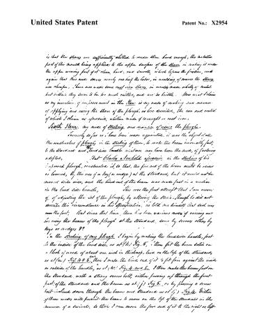
is that the shares are sufficiently shelled to render them hard enough, the metallic part of the mould being applied to the upper surface of the share in making it render the upper wearing foot of it clean, hard, and smooth, which lessens the friction, and again that this mode serves nearly one half the labor, in moulding, of course the shares are cheaper. I have also made some cast-iron shares in moulds made wholly of metal but believe they seem to be too much brittle, and are too brittle. Now what I claim as my invention of inferior merit in this share is my mode of making and manner of applying and using the share of the plough, as here described, the use and control of which I claim as aforesaid, whether made of wrought or cast-iron.
Sixth Item. My mode of stocking and manner of using the plough.
Formerly so far as I have been made acquainted, it was the object of all the constructors of ploughs in the stocking of them, to make the beam immovably fast, to the standard and land side handle whatever may have been the mode of fastening adopted.
But Charles Tenfold aforesaid in the stocking of his improved plough, constructed it so that, the fore end of the beam could be raised or lowered, by the use of a key (or wedge) at the standard, but it could not be moved side wise, and the hind end of the beam was made fast in a mortice in the land side handle.
This was the first attempt that I am aware of, of adjusting the rest of the plough, by altering the stock. Though he did not describe this circumstance in his specification, he told me himself that such was the fact. But since that time, there has been various modes of raising and lowering the beam of the plough at the standard, some by screws, others by keys or wedges &c.
In the stocking of my plough I begin by making the land side handle, fast to the inside of the land side, as at (Fig.) Fig. 5, then fit the beam solid on a block of wood of about one inch in thickness, laid on the top of the standard, as at (Fig.) Fig. 4 & 5. then I make the hind end of it to fit fair against the inside or outside of the handle, as at (Fig.) Fig. 4 and 5. I then make the beam fast on the standard, with a strong screw bolt, either passing up through the front part of the standard and the beam as at (Fig.) Fig. 5, or by passing a screw bolt inclined down through the beam and standard as at (Fig.) Fig. 4. Either of these modes will permit the beam to move on the top of the standard in the manner of a swivel, so that I can move the fore end of it to the right or left
Page 13.
United States Patent
Patent No.: X2954
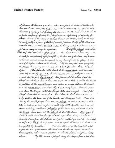
at pleasure. the hind end of the beam I then make fast to the inside or outside of the land side handle as at (W.) Fig. 4 and 5. with a screw bolt. My object in using this mode of applying and fastening the beam, on the standard and to the handle is for the purpose of affording the ploughman an opportunity of adjusting the plough. that is if the plough is disposed to work too shallow, it may be set deeper by merely putting a piece of leather (or wood) between the top of the standard and the beam, or rather the block under the beam, and if one piece is not enough put in as many as may be required. But if the plough should work too deep, then take some off the block and thus let it down, or raise it up until it works (or runs) precisely right for depth, or, the fore end of the beam, may be raised or lowered as much as may be required for every kind of work, by affixing the hind end of it higher or lower at the handle. By the use of this mode of adjusting the plough it may very soon be adapted to work after either horses, mules, or oxen. I then fasten the other handle to the mould board, with two small screw bolts as at Fig. 4 and 5. the two handles I connect together with two rounds see (W. P.) Fig. 4 and 5. Thus framed if it is desired to set the plough more to land, then I loose the upper screw bolt, by which the handle is fastened to the mould board, and drive a wedge between the handle and the mould board, as at (Z) Fig. 5 and as required. I loose the screw and drive the wedge, until the plough takes land enough. But if the plough should take too much land, then I loose the lower bolt and drive a wedge between the lower end of the handle and the mould board. Hence it is that by this simple process, I can alter my plough, so as to work deep or shallow take a wide or a narrow furrow with very little trouble, and to an absolute certainty, so that in ploughing if the team does not walk to suit the plough I can soon set the plough to suit the team. But again if I wish to set a two horse plough to work after three horses abreast, then I loose the beam from the handle and put in a block of about two inches thick as at (w. x.) Fig. 5. it may require more or less, the thickness of the block must be adjusted by practice. But then the end of the screw bolt, which confines the end of the beam, the block and the handle together must have a brace, applied, which I make fast up the handle, fifteen or eighteen inches above, By this means a plough may be changed from a two to a
Page 14.
United States Patent
Patent No.: X2954
three, or from a three to a two horse plough at pleasure, and with one, two, three, and even more than that, if required (which it sometimes is) the plough may be made to work after the team walking on the road or turf by the side of the open furrow, and, like the plough work well, and the only alteration required will be to put in a thicker block between the handle and the end of the beam. This has been required and done in marsh land where the horses so made, or ox could not walk in the open furrow.
The only use of the block which I put under the beam of my plough and on the top of the — standard is that it raises the beam that much higher from the ground and affords an opportunity of continuing the curve of the throat of the plough in a more complete form than it would be without at the same expense, and also if it be required to let the beam down, on the top of the standard the block may be dropped off without weakening the Beam.
I mostly fasten the block to the beam with nails
What I claim as my invention of improvement in this Stem, is, my mode of applying the beam to the standard, and my manner raising and lowering it on the standard, and my mode of fastening the end of the beam on the side of the handle, together with that of adjusting the fore end of the beam, by turning it to the right or left, and of making the hind end of it fast to the handle higher or lower, and the application of the blocks between the beam and the standard, and the beam and the handle, all of which I consider to be valuable improvements, and therefore claim the use and control of them as aforesaid.
Seventh Stem. Of the coulter if I apply the lock-coulter, I put it on a rib on the point of the share, which of course must be made of wrought iron. The only difference in my mode of applying the lock-coulter to the plough from what has been common, is that instead of making a mortise in the beam, for the upper end of the coulter to pass through and be made fast in, I make a mortise on the land side of the beam, by putting on a block of wood with a place cut in it which forms a mortise by the side of the beam, this block I fasten on with screw bolts, and of course I can give the coulter my inclination back that may be required, and fasten it tight with wedges in the usual way. The advantage of applying and
Page 15.
United States Patent
Patent No.: X2954
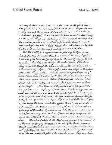
and using the locked coulter in this way is, that it lets the top of it to lean a little over to the land, which causes it to detach the furrow, slice from the sword (or sod) more easily than it would, if it was set vertical, or inclined a little over to the furrow; and again, it does not injure the beam so much as that of making a coulter mortise through it. But having satisfied myself, by actual experimenting, that it requires an increase of 33 ft. cent of power in the draught or more, to urge the plough along with a locked coulter than with sword coulter, properly fitted to it, my attention was principally directed to the latter.
But this I apply in a different manner from any heretofore in use. Instead of putting the coulter through a mortise in the beam, I apply it to the side of the beam, see (y) Fig. 4 and 5. My mode of fastening the coulter is this, I have holes made through the coulter shank. I then put a strong iron bolt through the beam, and the coulter at whatever hole is best suited to my purpose. I then apply a strong iron strap on the outside of the coulter, having a hole in it for the iron bolt to pass through, all of which I draw hard up with a nut, then having the lower end of this strap, made square or round in front of the standard in the sod, I bend it back behind the coulter and round in front of the standard or throat of the plough. Thus fitted on, if the coulter sets solid against the side of the standard and fast against the beam, it will be very permanent, and cut the sword or sod to the greatest possible advantage, and which to operate most beneficially, the edge should not be more than five inches forward of the throat and from half to an inch to the land. The effect is; that having the sword coulter thus applied, the point of the share when at work, runs from two to three and sometimes five or six inches in advance of the edge of the coulter, by which means it has the sword or sod so much raised, that it is very much strained, if not in the act of tearing, then the edge of the coulter slits it open in the very raised and scarred manner, as visible. That which I claim in this claim as my invention or improvement is, the mode of applying the coulter to the side of the beam, instead of through a mortise in it, and more especially, that of the particular manner of fastening the sword coulter to the plough, and using it so as not to cut the sod, until the point of the share has raised it up so as to have
Page 16.
United States Patent
Patent No.: X2954
it on a strain; all of which I claim the use and control of, whether in use, or even, or disposition of to others to use as used as aforesaid.
Witness:
Alex. McEntire 4
J. McDonald 3
Jason Davis
(6816 words)
E.A.
C.K.H.
Page 17.
United States Patent
Patent No.: X2954
DRAFTSMAN'S DIVISION.
All communications should be addressed to
"The Commissioner of Patents,
Washington, D. C."
2-328 a.
DEPARTMENT OF THE INTERIOR,
United States Patent Office.
Washington, D. C., 189—
SIR:
The printed copies of Patent No. G. Davis
are exhausted.
As soon as reprinted a copy will be mailed you to complete your order.
By direction of the Commissioner:
Very respectfully,
Chief Clerk.
3148b6-97-5m
About this record
- Patentee
- DATAMP
- Date
- the Name and Date index of patents, DATAMP, Burke's List of Patents (1847)
- Invention
- DATAMP
- Listed in
- the Name and Date index of patents, DATAMP, USPTO records, Jim Shaw's X-patent list, S. A. Elliot's printed list of patents, Burke's List of Patents (1847)
- The sources give different dates; the date shown is the one most of them agree on.
- S. A. Elliot's printed list of patents gives the same name and date.
- Burke's 1847 Patent Office list gives the same patent.