

Drawings and documents
USPTO scan
The patent as scanned by the USPTO
-
 Page 1
-
 Page 2
-
 Page 3
-
 Page 4
-
 Page 5


U.S. Patent and Trademark Office · Google Patents
Show the transcription Hide (1,398 words)
Machine transcription (LightOnOCR) of the pages as scanned by the USPTO, most of them the handwritten copies made when the records were restored after the 1836 fire. Not checked; it can misread handwriting, so compare it with the scan.
Page 2.
United States Patent
Patent No.: X4830
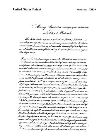
Amory Amosden, a citizen of the United States
Letters Patent.
The Schedule referred to in these Letters Patent and making part of the same, containing a description in their own words of the said Amory Amosden himself of his improvement in the machine for making cooper's staves ready for the tree hoops.
Fig. 1. The block carriage & saw. A. The block saw runs in a perpendicular manner like that of an ordinary saw-mill, and faces the sawmill saw directly back of the head block, so that when the block carriage receives the plank intended to be worked into staves, the block saw cuts it smoothly (the plank standing upright and on its edge) and the saw strikes and cuts it off near the letter B. B. the block carriage has four motions: 1st by being moved by the swivel dogs C.C. it plays towards the block saw where the stick placed upon it is bitten; then by springs placed under the carriage B. (which cannot be represented in the straight) as soon as the notch gauges 1.2.3.4.5 attached to the main saw-mill carriage D. have passed the swivel dogs C.C. then the springs 1.2.3.4. (which are sprung by the last operation) instantly throw the block carriage B. to its first position; being now out of gear & detached from the saw-mill carriage D. the weight B. suspended by the rope F, draws the block carriage until the end of the plank strikes the block gauge G, which measures it the proper length for a stave; the block saw is all the time running and is ready to cut whenever the notch gauges begin to take effect on the swivel dogs at which time the block carriage begins to move towards the saw; it then begins to cut & continues precisely the same operation until the plank
Page 3.
United States Patent
Patent No.: X4830
is worked up which will be in the same length of time that the saw mill carriage runs through. When the carriage D returns, having its arm H extended, it takes the block B by the band J, and leads it back to the place from whence they both started, at which time the carriage D is ready to receive a part of D’s load or the plank just unwound. — K the keeper or key retains the carriage B, after the plank has moved by the gauge C, until the plank is unwound in two parts. — L the sloping dog that holds the plank while sawing. — M the lower A, the upper pulleys through which the rope F runs. O the staple to which the rope is attached. P P, the long slits for the carriage B. — a, the spikes which keep the plank from slipping. — b. b. the short cross slits — C the perpendicular arms or holdfasts that keep the plank erect on its edge. d. d. govern the gauge C for the desired length of the stave.
Fig 2. A cylinder saw for sawing staves of any size. — A the cylinder is composed of cast iron & maybe of any size according to the size of the stave wanted; for instance, for barrel staves it will require about 3 feet from the back end to the muzzle & about 22 inches in diameter. — B the tube end, extends from 10 to 12 inches in length including 3 or 4 inches thru’ the back end into the inside of the cylinder thru’ which the shaft runs & serves for the gear on nearest the saw — two as well as one of these may be hung on the same shaft by turning the teeth the other way, having in that way two sets of teeth opposite each other. — C the saw plate will be from 9 to 10 inches wide & is placed from 1 to 1½ in to the saw. D the feeder is an iron or steel screw about about 7/8ths of an inch in diameter with a thread gaining in every successive revolution about one fourth an inch which runs into the shaft & extends to the back end of the carriage.
Fig 3. In case of 2 cylinders on the same shaft, one of the screws must
Page 4.
United States Patent
Patent No.: X4830
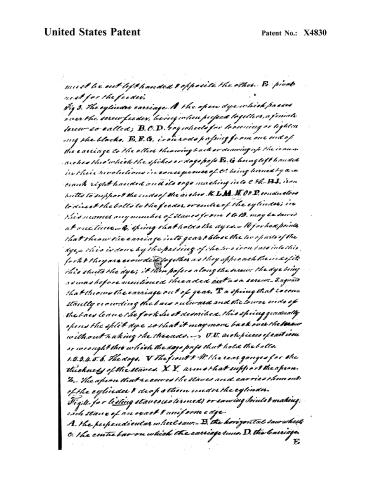
must be not left handed & opposite the other. E. pivot next for the feeder.
Fig 3. The cylindrical carriage. A the open dye which passes over the screw feeder, being when pressed together, a female screw so called; B, C, D. dog wheels for loosening or tightening the blocks. E, F, G. iron rods passing from one end of the carriage to the other throwing back or drawing up the iron wickets H which the spikes or dog posts E. G. being left handed in their revolutions in consequence of C. being turned by a crank right handed and its ergo matching into C & H. B I. iron bolts to support the ends of the wickets K, L, M, N, O, P. conductors to direct the bolts to the feeder, or centre of the cylinder; in this manner any number of slivers from 1 to 13. may be sawed at one time. Q. spring that holds the dyes. R. for her points that throw the carriage into gear & block the two parts of the dye, this is done by the passing of the two iron bars into this fork & they are crowded together as they approach the ends of it this shuts the dye; it then passes along the screw, the dye being screw before mentioned threaded out as a screw. S. a guard that throws the carriage out of gear. T. a spring that is constantly crowding the bars outward and the lower ends of the bars leave the fork as it descends, this spring gradually opens the split dye so that it may move back over the screw without taking the threads. U, V. arch pieces of cast iron or wrought iron which the dog posts that hold the bolts.
1. 2. 3. 4. 5. 6. The dogs. V the front & W. the rear gauges for the thickness of the slivers. X Y. arms that support the apron. Z. the apron that receives the slivers and carries them out of the cylinder & drops them under the cylinder.
Fig 4. for listing slivers (determined) or sawing joints & making each sliver of an exact & uniform edge.
A. the perpendicular wheel saw. B. the horizontal saw wheel. C. the centre bar on which the carriage turns. D. the carriage.
E.
Page 5.
United States Patent
Patent No.: X4830
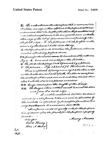
E. The rack whereon the staves from 1 to 6 or more are placed at a time; one edge is then applied to the perpendicular saw and carried throu' the length of the stave the frame turns easily and is then brought down to the horizontal saw, so that the other edge of the lot of staves are sawed precisely like the first edge. F. the follower which presses on the staves by the hand & hold them steady.
G. Hold fast with teeth to retain the follower wherever wanted after being pushed down.
H.H. frame for the circular saws. J.J. screws to direct the centre bar.
Fig. 5. A. Case and director for the Jointer.
B. The stock which plays back & forward by a pitman.
C. The pitman. Figs. 1, 2, 3, 4, 5, 6, 7, 8. The Jointer irons.
These are placed, & facing one way & the other so that as the Jointer moves back & forth, the staves move from the centre first toward one end and then toward the other & all the staves are placed as desired.
D.D. Gauge screws for the length of the staves.
E.E. The gauges where notches are cut to direct the stave and give it a bevel edge.
It must be understood that this Machine is moved by water power & the one now in operation by the inventor is attached by principles familiar to every Mechanic to a common saw Mill.
Where power would do equally well for the preparation of staves after the plank for the purpose is properly sawed.
Witnesses
Shad. N. Fleming
Peter A. Mower
Amory Amnden
12152 h.
Ex. 1.
Ch. 11.
Published accounts: journal notice
Notice in the monthly list of patents
Journal of the Franklin Institute, vol. 5 (1828), p. 139 · View the page
In the machine for making Cooper's staves, ready for the tresshoop; Amory Amsden, Bloomfield, Ontario County, New York, July 27.
DATAMP: illustration
Illustrations from DATAMP
DATAMP (Directory of American Tool and Machinery Patents), via the Internet Archive · Archived DATAMP page
About this record
- Patentee
- DATAMP
- Date
- the Name and Date index of patents, DATAMP, USPTO records
- Invention
- DATAMP
- Listed in
- the Name and Date index of patents, DATAMP, USPTO records, Jim Shaw's X-patent list, the Journal of the Franklin Institute, S. A. Elliot's printed list of patents, Burke's List of Patents (1847)
- S. A. Elliot's printed list of patents gives the same name and date.
- Burke's 1847 Patent Office list gives the same patent.