

Drawings and documents
National Archives restored drawings: drawing
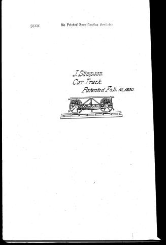
James Stimpson's Patent Drawing for an Animal Rapid Rail-Road Carriage

National Archives, Restored Patent Drawings (Record Group 241) · Full-size scan at the National Archives · Catalog record
Show the text on the drawing Hide (159 words)
Words on the drawing as machine-read by the National Archives; not checked. Useful mainly for searching.
106. RAILWAYS. / 3. / Exterior Mountings & Fittings / [122] Trucks. / Patented 16Teby 1830 / $2- / CLASSIFICATION / a. / a. / 5833x / b. / b. / JAMES STIMPSONS / ANIMAL RAPID RAIL-ROAD CARRIAGE / Oily Battemore State of D. / on this 3111 day before / Justice oft the peace in and for said City personally / a ppeared James timpson of Baltimore and made / Solemn oath that he is interested as inventor other in a pate / -ent for the a application of Horse or animal / power for propelling camages on on Rail wayson roads, / ipued thin him and dated with 16th of February 1830; thereto, and / he verily believes a true delineation oft insen- / drawing the references he are, / describe a in the saia letters patent. / Drann For you / a,a. Aside view of the frame of the carriage. / b,b, The road wheels. / C.C. Antifriction wheels. / d,d The revolving endless floor. / e,e. Rollers under the floor.
USPTO scan
The patent as scanned by the USPTO
-
 Page 1
-
 Page 2
-
 Page 3
-
 Page 4
-
 Page 5
-
 Page 6
-
 Page 7
-
 Page 8


U.S. Patent and Trademark Office · Google Patents
Show the transcription Hide (2,746 words)
Machine transcription (LightOnOCR) of the pages as scanned by the USPTO, most of them the handwritten copies made when the records were restored after the 1836 fire. Not checked; it can misread handwriting, so compare it with the scan.
Page 1.
5833X
No Printed Specification Available
J. Stimpson.
Car Truck.
Patented Feb. 16, 1830.

Page 2.
James Simpson Baltimore Maryland Letters Patent.
The Schedule referred to in these Letters Patent, and making part of the same, containing a description, in the words of the said James Simpson, himself, of his improvement, in the application of horse or other animal power, for propelling carriages on Railways or Roads.
To all to whom these presents shall come.
Be it known that I James Simpson of the City and County of Baltimore & State of Maryland have invented a new & useful improvement in the application of horse or other animal power for propelling carriages on railways or roads, which improvement consists in this, that the horse or other animal travels and rides at the same time on the carriage which by this power is moved, & any degree of velocity can be imparted to the carriage, which never tires by a steady but moderate movement of the animal which of course enables him to perform a greater length of time under any speed of the carriage, than he otherwise possibly could if its rate of speed depended, as it ordinarily does, entirely on the degree of activity of the animal. To gain this great desideratum, the construction or make of the machine or carriage must be as follows, viz; There must be two main shafts or axles of sufficient size and strength of iron or other materials, with four wheels fitted to run loose, yet close on said shafts at such distance as will fit the rails of the road on which they are intended to run, there is to be fixed fast on said axle, a nut or other fixture on the outside of said wheels, to prevent them from running off of the shafts, to which nut or fixture, is united a dog, fall, or catch on a centre or pin against which a spring acts or fulcrum acts and acts sufficiently to throw said fall catch
J. W. Holton
Page 3.
catch or dog into ratchet teeth fixed on the side of the hub of said wheel next to the fall, by which means when the shafts are turned round by the power of the animal, one end of said fast being fast to the shaft, thru' the intervention of the nut or other fixture, the other end act against the teeth of the ratchet wheel, or will cause the road wheel to revolve as fast as the shaft; at the same time in passing a curve in the railway, the wheel on the outer circle is at liberty to revolve faster than the shaft or the wheel on the inner circle of the rail; hence the wheels are always at liberty to advance, but cannot recede without turning the shaft with them; said falls or ratchet teeth may also be placed on the inside of the wheels if more convenient.
Furthermore, if one fast pulleys or drums are to be fixed upon said axles within the road wheels at such a distance as to bring them directly under the animals feet, & sufficiently thin or wide to receive bands six to twelve inches wide or any other width; & of such diameter compared to that of the road wheels as will produce any rate of speed, desired.
On these bands is to be laid a floor, each plank or board of which is to extend across & beyond the bands on both sides two inches more or less & fastened by iron bolts, with thin wide heads, in the range of the belt heads, or directly under them.
Grooves must be turned in the drums or pulleys for the annular of the heads of said bolts, so that they may not raise the bands from the drums as they revolve round them; the bolts are to extend about half an inch more or less into the boards or planks above said bands, with a nut to be screwed down close into a well or hole large enough for said nut to turn in; and after being forced down tight with a wrench, a plug is to be driven in tight over it to prevent its coming off, and the animals feet from touching it; said bands are to be thoroughly covered with boards or planks, laid across one foot wide more or less, each having two to four bolts in the middle.
Page 4.
middle of them all on a line with each other, by reason of which they will pass round the drums without varying the tightness of the bands without any liability of splitting the boards or planks, which may also be fastened to the bands by wood screws nails or other means in like manner. The two main axles on which the bands and floor revolve must be at a distance sufficient to prevent the animals feet from extending beyond their centres either way. Between the drums on the main axles must be placed one or a double row of pulleys two on each shaft near the outer ends, & directly under the horses or animals feet, and bands in a line with those on the main axle. The upper peripheries of which must be on a line horizontal with those or such a little below, & as near to each other as they can be without touching for the support of the revolving & flexible floor, & which will effectually prevent the floor from sinking beneath the head of the animals feet. Spacious of pulleys or drums under each band be used, the outside row should extend to the outer edges of the bands & be from inch or thick if for ten inch bands, & lie as near to each other as they can, leaving a sufficient space for the shaft of the inside row to pass between the peripheries of the outside row without touching. The pulleys of the inside row should be six inches thick, being so turned that they shall just clear the inside of the outside pulleys or drums, those two next to the main axles should be lagged in the middle reaching to, but not quite touching the insides of those on the main shafts or axles, & raised no much above those on each side, as the thickness of the bands, by which means they will receive & support the horses' and floor, as it revolves past the first or setting or hollow of the outside drums. The centres of all the middle or outside pulleys should rest on friction wheels, either one, two or three, if one wheel only there must be a slot in the axle to support the shaft above it if only one or two, they must lay side by side on a horizontal line.
Page 5.
line, their centres sufficiently distant to let each pass the periphery of the other without touching, in which position they leave a place for the pulley shaft to rest in without other support; and thirdly, if on three rollers, two must be fixed in the frame or side of said carriage, one on each side of the shafts of the pulleys, and the third directly underneath it on which the pulley shaft is to revolve and bear its whole weight, or the pulleys may rest on their own bearings, without any friction rollers whatever. A frame of sufficient height, length and width is to be made to receive the animal or animals &c. and of sufficient depth to receive the friction wheels of the pulleys under the floor bands, & a part of the sides, at least must be double to support the centres of eight other friction wheels (but if the machine is made without any friction wheels, there must be two main timbers running thri' & extending beyond the wheels each way for their protection; & also in this particular for that with friction wheels) their under edges will be above and rest upon the boxes of the main axles of the road wheels; the side posts must pass down sufficiently below these side timbers or rails to receive uprights, on which must be placed two rails laying parallel to each other & reaching nearly from one axle to the other, & of sufficient width & thickness to sustain the pulley shafts under the floor bands on this frame the weight of the pulleys & animals rest. The eight friction wheels are for the whole frame to rest upon, & their under peripheries move with and upon the axles of the first described road wheels said friction wheels may be of any dimensions in diameter or thickness, which may be found most convenient to use with their centres as before described in the second proposition, or the carriage may rest upon boxes without any friction wheels whatever. The road wheels are made to revolve by the horse or other animals moving at any rate of speed, upon the revolving floors, there must also be inside and near each end
Page 6.
end of said main axle another friction wheel, located in the frame of the carriage to sustain them in their places under the continuation of the floor bands, & also to keep the axles in the centres of the castlings of the eight friction wheels on which the carriage. These friction wheels will always keep the two axles on a parallel line with each other but will admit the shaft or axle to be forced forward by the bands being loose by a guide running on the road before the carriage, for that purpose or otherwise to turn on any curve in the road that is to say, neither way of the forward axle can recede or move back by reason of the friction wheel behind, but may advance, so likewise the after axle cannot be moved forward, for the centres of the friction wheels being fixed in the frame directly before, prevent it, but it may be moved backwards so as to conform to the front axle in turning a curve in the road. All the friction wheels to be made of a thickness, conformable to the magnitude of the weight they are intended to support & of a diameter as extended as the nature of their application will conveniently admit, their centres must always conform in length & diameter to the tension of gravity in all cases applicable to their intended use. It is also intended in case roads or railways are not entirely level, or horizontal throughout, but have planes & inclines to be constructed the tow carriage as to enable the same animals to take up the inclines as much as they can draw on a level at an advanced speed by means of a reduction of the speed of the tow carriage conformably to the amount of gravity of the incline which it is necessary to ascend; At the summit the speed is again renewed, the resistance being lessened, or the speed of the carriage is again in union with that of the animals as at first graduated. This object is accomplished thus, the drums or pulleys on the main shaft on which the bands or chain floors revolve, are to be fitted with shafts loose with conformation or iron boxes inside of these pulleys or drums a foot man or dog is to be fixed to the shaft, then
Page 7.
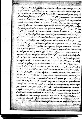
a bayonet into be fitted on to said shaft, the forks of which pass the said pulleys, and come in contact with the fast arm or dog on the shaft, I will then cause the pulley to be fast or a fixture to the main shaft, of course one cannot turn without the other, but by sliding out the bayonet the forks lose their hold and then all the drums become sufficiently loose to revolve upon the main shaft of the carriage, by doing which all motion of the carriage occurs, as the lane or floor on which the animals travel revolve round without moving the shaft to revolve but for a small bevel or spur pinion wheel on the outer side or edge of the bayonet hub being made to come into gear at the same time the fork below the fast dog on the inside of the pulley or drum, and the drum is thereby free from the carriage or shaft, to communicate any other speed or motion to the carriage which is wanted, or the following other application of gears will do, with a small bevel or spur gear fixed upon a small shaft, laying fore & aft between the floor and road wheels, reaching if necessary to the other axle, on which shaft is also a sliding bevel or spur gear made to come in contact with a gear or made fast to the inside of the road wheels, & on said wheels so fastened to the road wheels may be one, two, three or four rows of teeth, more or less, on wheels one without the other, so that in whichever line or row of teeth the small slide gear is made to come in contact with, the speed of the carriage will conform to, for instance, if the gear on the face of the bayonet hub, has ten teeth on it, and the small gear on the shaft parallel to the floor has ten also, the slide gear on the same shaft having ten, in all these there is no gain or loss of speed, but the last mentioned slide gear being made to come in contact with the outer row of teeth on the road wheels which row we will say has forty teeth in it, it will reduce the speed of the carriage to the actual speed of the animal, at the previous effect
Page 8.
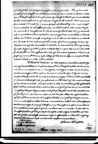
Speed of the carriage was sometimes faster. The aforesaid small gear shaft must be entered in two slits or boxes which must be fastened to a frame by itself & that again attached to the main frame of the carriage not to allow it to move forward & back by means of a fork holding the main shaft & connected to the side frame so that when the main shaft is moved to conform to the curves of the road, the gears will all maintain their relative bearings & connections with each other, but this is only necessary when the main axles are allowed to vibrate to the curves of the road; if it is necessary to convey the power of the animals to all the road wheels, it may be done by a pulley projecting from the pulley under the main band & fast to it on the opposite side of the above gear, with a band passing over it to over a pulley of the same size, made fast to the road wheel on the other axle.
What I claim in the aforesaid mentioned carriage as my invention or improvement is its application to horse or other animal power, whereby he or they can travel in & upon said carriage either upon roads or railways, & by so doing impart a power to move said carriage either with accelerated or diminished speed, compared with that of the actual motion of said animals. I also claim the invention of the application of friction wheels to sustain the weight of said animals & the weight of the pulleys under the flexible floors; & the double rows of pulleys or drums under each band. Also the application of friction wheels to support the weight of the frame or animals, apparatus, & load, connected with, & about said frame said carriage being of itself a new & useful improvement, as locomotive carriage before unknown or used. I also claim the application of the gear principle whereby a variation of the speed of the carriage motor or lip is effected without varying that of the animals as herein before described.
Witnesses
James Stimpson
2724 205 (Patent May 1860)
Published accounts: journal notice
Notice in the monthly list of patents, with remarks
Journal of the Franklin Institute, new ser., vol. 5 (1830), p. 296 · View the page
20. For a machine called the "Animal Rapid Rail-road Carriage;" James Stimpson, Baltimore, Maryland, Feb. 16.
Remarks. We know not the number of true and original inventors or discoverers of that kind of rail-way carriage in which the horse is to ride, walking upon a moveable endless floor running upon rollers, which are so geared to the wheels as to cause the carriage to travel at a rate many times exceeding that of the motion of the horse upon the floor. We have before alluded to it, as it has been previously patented, and has also been displayed in various newspapers, by means of a large wood cut. In all its essential features the carriage now patented resembles those to which we allude. It is proposed to make a very liberal use of friction wheels to support the gudgeons of all the revolving parts; there are also some other minor arrangements made which may be new, but it is not for these merely that the patent is taken, as will be seen by the claim. "What I claim in the before mentioned carriage as my invention or improvement, is its application to horse or other animal power, whereby he or they can travel in and upon said carriage either upon roads or rail-ways, and by so doing impart a power to move said carriage with accelerated or diminished speed, compared with that of the actual travel of said animals." "I also claim the application of the invention of friction wheels to sustain the weight of said animals, and the weight of the pulleys under the flexible floor; and the double rows of pulleys, or drums, under each band." "Also the application of friction wheels to support the weight of the frame, animals, apparatus, and load, connected with and about said frame; said carriage itself being a new and useful improvement as a locomotive carriage, before unknown or used." "I also claim the application of the gear principle, whereby a variation of the speed of the carriage, more or less, is effected without varying that of the animals as hereinbefore described." The gear principle alluded to in the last claim, is the placing upon the carriage wheel to which the driving power is applied a number of toothed wheels, concentric with the axis, so that by shifting the driving wheel from one to the other the alteration required will be effected.
About this record
- Patentee
- DATAMP
- Date
- the Name and Date index of patents, DATAMP, USPTO records
- Invention
- DATAMP
- Listed in
- the Name and Date index of patents, DATAMP, USPTO records, Jim Shaw's X-patent list, the Journal of the Franklin Institute, Burke's List of Patents (1847)
- Burke's 1847 Patent Office list gives the same patent.