

Drawings and documents
National Archives restored drawings: drawing
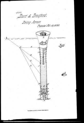
S. Short and N. Bradford's Patent Drawing for a Submarine Explorer

National Archives, Restored Patent Drawings (Record Group 241) · Full-size scan at the National Archives · Catalog record
Show the text on the drawing Hide (34 words)
Words on the drawing as machine-read by the National Archives; not checked. Useful mainly for searching.
HYDRAULIC ENGINEERING. / 82 Diving Armor. / 150 / S.SHORT & N.BRADFORD'S 0 / Submarine Explorer. / Patented 18ᵗʰ. Feb. 1830. / 5834-X / at / is / It
USPTO scan
The patent as scanned by the USPTO
-
 Page 1
-
 Page 2
-
 Page 3
-
 Page 4
-
 Page 5


U.S. Patent and Trademark Office · Google Patents
Show the transcription Hide (1,251 words)
Machine transcription (LightOnOCR) of the pages as scanned by the USPTO, most of them the handwritten copies made when the records were restored after the 1836 fire. Not checked; it can misread handwriting, so compare it with the scan.
Page 1.
5834X
Short & Bradford.
Diving Armor.
Patented Feb. 18, 1830.
THE GRAPHIC CO. PHOTO-LITH. 39 & 41 PARK PLACE, N.Y.
Page 3.
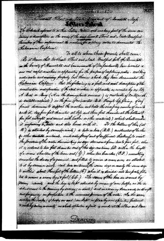
To facilitate the motion of the limbs in walking and working, it is desired the moving of the arm the motion horizontal spiral wires instead of hooks, and think them preferable as they admit of great freedom and variety of motion, and perhaps might be found most convenient for the legs also. The machine is worked by means of weights (H, H, H) suspended by chains from hooks (F, F) screwed into a hoop and furnished with a spring to prevent the chains from being easily disengaged. To aid, it may be necessary or convenient to suspend weights from each of the hooks, owing bolts which are fitted in the hoops inside and outside being thrown on each hoop outside and perhaps the same inside. To prevent being elevated and depressed by the undulations of the water the hoop is contracted by folds for the distance of six feet from the buoy, so that the buoy may rise with any ordinary wave without affecting the lower part of the apparatus, and to restore its contraction when the wave subsides three spiral wires (like G, G, G) of sufficient strength to effect this object without moving the machine are placed on the outside and secured to the hoops by screws or rivets and extend the distance of six feet downward. To prevent the rope from being constrained in any particular part, chains are extended from top to bottom and attached to the said hooks or rings, and made to bear equally on all the hoops, as long as the spiral wires from which place the buoy they are so slackened as not to take effect till the hoop becomes extended when they do, and prevent a strain of the rope. About two thirds of the distance from the top to the bottom of the buoy, there is a platform which was intended to be represented by the figure D, exhibiting a section of the buoy, having in its centre an aperture (D, D) of the diameter of two feet around which is an iron railing on the top of which is a windlass (E, E) on this platform the men who are the operators stand. Thro this aperture the operator descends by stepping on the hoops and carries with him fastened around his body a rope from the windlass and swings himself in the parts of the bottom adapted to his body and limbs. The windlass and rope facilitate and hasten his ascent in case of sickness or accident. To enable him to see external objects three lights of thick glass (as K, K, K) are put in one in front and one on each side, and set in iron hoops or copper frames and secured to the hoop by screws (N, N) rivets. To enable him to use his hands with ease a pair of leather gloves or mittens are fitted by screws or rivets to the inside of the iron hoops of the doors, and the preference of the nation may check circulation and occasion cold. It will be necessary to warm them, and to prevent the pressure of the water from hurting
Page 4.
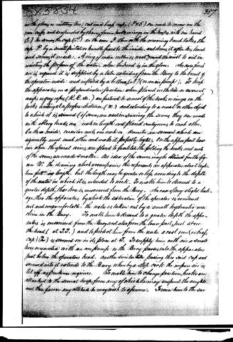
in the gloves or mittens, two (central) brass cuffs (P+Q) are made to verse on the two cuffs and suspended by chains from hooks or rings in the chaps, with one hand (R) he draws the cap (C.) on the arm & then with the remaining hand takes the cap P. by a small point or handle fixed to the inside, and draws it after his hand and through it inside. A ring of india rubber is well ground in the met to aid in resisting the pressure of the water, when the hand is in the glove. An air pump is required it is supplied by a tube extending from the Buoy to the breast of the operator inside and inflated by a bellows (T) (or an air pump). To keep the apparatus in a perpendicular position when placed in the side or current (may, in any seas, (R.R. &c.) are fastened to several of the hooks, or rings in the heels, leading at a proper distance (X) and extending to a vessel or other object to which it is secured (if there are any in drawing the scows they are made with oblong heads an inch in length and placed contiguous to each other. On these inside, circular nuts, one inch in diameter are screwed which are apparently meet each other and make it perfectly tight. On the upper part there are three the spiral wires are placed to facilitate the folding the heads and nuts of the scows are made smaller. An idea of the various may be obtained from the figure No. the drawing which accompanies this represents an apparatus about eighteen feet in length, but the length may be greater or less according to the depth of the water in which it is intended to work. To enable him to descend to a greater depth, the line is unsecured from the Buoy. In case of any slight leakage, the apparatus by which the exhalation of the operator is rendered not and uncomfortable, the water is taken out by a small hydraulic machine in the Buoy. To enable him to descend to a greater depth, the apparatus is unsecured from the Buoy and also from the lower part, just above the head, (at R.T.) and to protect him from the water a cast iron (or brass cap) (Z) is screwed on in its place at T. To supply him with air, a small hose connected with an air pump in the Buoy passes into the apparatus just below the operator's head. Another similar tube passing through said cap and screwed into it extends to the Buoy, whereby a stop cock the impure air is let off as prudence requires. To enable him to change position, hooks are attached to the several hoops, from any of which he may suspend the weights and thus form any attitude he may wish to assume. To raise him to the surface
Page 5.
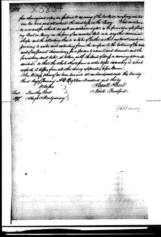
few when required, ropes are fastened to as many of the hooks as may be, and tied over his head and attached to the windlass in the Barge. What we claim as new and for which we ask an exclusive right, is the formation of the floating Boat or Barge in the form of an inverted Bell or in any other convenient shape and the attaching there to a tube of leather or other material made impervious to water and extending from the surface to the bottom of the water and of sufficient dimensions for a person to ascend and descend and the furnishing said tube, at bottom with the kind of doors or covering above described, so that the whole shall form a watertight canoe or bag in which respects, it differs from all other diving apparatus before known.
In Witness Whereof we have hereunto set our hands and seals this twenty third day of January A.D. Eighteen Hundred and thirty.
Witnesses
Timothy Reed
Hugh Montgomery
Asaall Short
Noah Bradford.
Published accounts: journal notice
Notice in the monthly list of patents, with remarks
Journal of the Franklin Institute, new ser., vol. 5 (1830), p. 298 · View the page
25. For a diving apparatus called the "Submarine Explorer;" Sewall Short and Noah Bradford, Barnstable, Barnstable county, Massachusetts, February 18.
Remarks. This diving apparatus consists of a hollow buoy which floats in the water, and is in form like an inverted bell. Both ends of this buoy, or bell, are open. It must be made of light materials, and covered with leather, or other substance, so as to render it impervious to water. There is a platform, or seat, around it on the inside, to accommodate the assistants. To the lower end of the buoy is attached a flexible water tight tube, which may be two feet in diameter, and must extend down nearly to the bottom of the water. The tube is distended by strong iron rings, and sunk by means of weights; its lower part terminates in a water tight dress, fitting the legs and arms, and kept distended, like the main tube, by suitable rings; light is admitted through openings occupied by strong panes of glass. The whole apparatus thus forms a bag open at top, but closed below. It is to be moored in a secure way, and to be of sufficient length to allow it to rise and fall with the motion of the water, without disturbing the operator. A windlass is provided, which crosses the floating buoy, and is intended to draw the diver up when necessary, an air tube to force air down, and an hydraulic tube to pump any water up which may accidentally enter, are also appended. The claim is to the general arrangement and construction of the apparatus as above described. We have omitted the description of some of the auxiliary apparatus, as unnecessary to our purpose. An instrument of the kind de scribed would probably answer well in places where the water was not very deep; at great depths, the operator would find it extremely difficult to move about, as the large leather tube, must, to a certain extent, move with him; the pressure of a current, running with moderate force only, would be immense upon a tube of the requisite diameter, when extended to a great length. The dress intended to fit the arms, and the lower parts of the body, is very similar to what has been already introduced, and used with some success. Any flexibility in the main tube, to allow it to rise and fall with the motion of the water, must exist at the upper part only, as the pressure at considerable depths would be such as to prevent any such motion; the tube must there be so kept out as to be incapable of being shortened by the folding in of the leather, or otherwise the buoy, or flat, would be drawn under water.
About this record
- Patentee
- DATAMP
- Date
- the Name and Date index of patents, DATAMP, USPTO records
- Invention
- DATAMP
- Listed in
- the Name and Date index of patents, DATAMP, USPTO records, Jim Shaw's X-patent list, the Journal of the Franklin Institute, Burke's List of Patents (1847)
- Burke's 1847 Patent Office list gives the same patent.