

Drawings and documents
National Archives restored drawings: drawing
R. Miller's Patent Drawing for a Thrashing Machine

National Archives, Restored Patent Drawings (Record Group 241) · Full-size scan at the National Archives · Catalog record
Show the text on the drawing Hide (74 words)
Words on the drawing as machine-read by the National Archives; not checked. Useful mainly for searching.
2- / 130. THRASHING. / Entered. / [159] ThrashingMach a cylo / 5897-+ / R o МПШИ ER / ThrashingMachine / Frame / Patented 15 March 1830g / Cylinder of Beaters / 3a / Bed- / Hoppen. A. Feeding Rollers.B. Cloth / The multiplying wheel or Driving pulley / OF / Strickland Del' / Patent Office 12 Ian 1839 / Made under the direction of the Commifram / of Patents in conformity with Act.3Mar 1837 / Hd Whoor h / Commiproner of Patents,
USPTO scan
The patent as scanned by the USPTO
-
 Page 1
-
 Page 2
-
 Page 3
-
 Page 4


U.S. Patent and Trademark Office · Google Patents
Show the transcription Hide (958 words)
Machine transcription (LightOnOCR) of the pages as scanned by the USPTO, most of them the handwritten copies made when the records were restored after the 1836 fire. Not checked; it can misread handwriting, so compare it with the scan.
Page 1.
5877X
R. Miller
Thrashing Mach.
Patented Mar. 15, 1830.
Section

Page 2.
Mar 15 1890
Benedolph Miller
Letters Patent X5877
The Schedule referred to in these Letters Patent and making part of the same containing a description in the words of the said Benedolph Miller himself of his improvement on the threshing Machine.
Be it known that I Benedolph Miller of Maricota Llanocoter County, Pennsylvania have invented an improvement in the machine for threshing grain which is described as follows. This machine consists of 1st the frame. 2nd the cylinder of beaters. 3rd the bed 4th the hopper for any cotton & cloth. 5th the pulleys & shafts so for driving the machine. 1st The frame is three feet six inches in length, the side pieces 12 inches wide & under each side piece is a cross piece or girth tenoned into the end posts. The end posts are 3 feet 6 inches high with four end pieces or girths; the two lower ones put in with a tenon & mortice from the bottom & the two upper ones let in with a dovetail from the top. At the lower end & at one side, the girths extend beyond the frame 9 inches, & an upright is framed into the upper & lower girths so as to admit of a multiplying or driving wheel to be placed & run therein. 3rd The cylinder of beaters is made to extend along the frame having two circular wooden heads about 15 inches in diameter & two inches thick fixed one near each end on an iron shaft made to turn on trapezoidal places on the frame's six (smoothly) dovetail openings are made on each of these heads to let in the ends of the beaters, which have trapezoidal dovetail heads made to slide up & down in said openings. Three of these beaters are octagonal, one 3 & a half inch in diameter & three are one inch by one & a half made of wrought or cast iron. The two front gears are set forward to bring the face of the beater to about 3/4 of an inch. The square beater is fastened with a square tenon into the dovetail so as to swing the same. The rectangular beater has a round tongue to connect the beater to play roundly & prevent them from chipping.
Page 3.
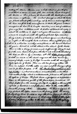
cutting the straws. There is now a loop about one fourth of an inch thick is drawn on each of the two circular heads to confine the heaters in their places, and the heads with the heaters form a short iron drum or cylinder. The socket openings in which the heaters are placed admit of their working up and down in such a way that the lower ones fall to the circumference to strike the grain and straw conveyed on the bed (to be hereafter described) or in case of resistance from any hard substance will be pushed up toward the centre, and admit the substance to pass and not injure the machine. 3d. The bed is made to correspond with the cylinder of heaters before described being a section of a circle in which is placed a square iron bar having an angle at the end of the heater and down three eighths of an inch thick to a shoulder and they are so placed in the bed as to beat out the grain, but not to cut the straw when struck by the heaters. There is also a lining of wood made sufficiently strong to support the iron bars which form the bed and into which the shoulders of the bars are let in by a mortice. 4th. The hopper feeding rollers and cloth are made in the usual way and the latter turned by means of straps, cords, and pulleys connected with the driving pulley and cylinder of heaters. There are also two feeding rollers, the lower one is fixed but the upper one rises and falls having a spring over it for that purpose. 5th. The Multiplying wheel or driving pulley is about 20 inches in diameter and three inches thick also another pulley about 8 inches diameter placed on the axle with the cylinder of heaters. The first turns on guides as supported in boxes in the extended girdles of the frame before mentioned. A strap passes from the driving pulley to one fixed on the end of the cylinder of heaters and a cord passes from that to the roller that turns the feeding cloth. Operation: The straws of grain being put into the hopper descend on the feeding cloth. The driving pulley being turned by a hand or any other power geared for that purpose brings forward the grain on the feeding cloth as then passes between the feeding rollers to the bed, is struck by the cylinder
Page 4.
X5877
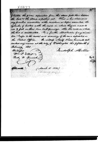
If heated, the grain separated from the straw falls through between the bars & the straw is pushed out. What is here claimed as my peculiar invention is the machine as before described, the cylinders of beater with the mode in which they are made to rise & fall in their slow tail openings. Also the mode in which the bea is constructed. For a further illustration of my invention I refer to the model and drawing of the same deposited in the Patent Office. In witness whereof I have hereunto subscribed my name at the city of Washington this fifteenth of February 1830.
Witnesses
Wm P. Elliot
Robt W. Fenwick
Rundolph Miller
Ex 4
2.8.11
(March 15, 1830.)
(No entry made)
Published accounts: journal notice
Notice in the monthly list of patents, with remarks
Journal of the Franklin Institute, new ser., vol. 5 (1830), p. 369 · View the page
23. For a Thrashing Machine; Rudolph Miller, Marietta, Lancaster county, Pennsylvania, March 15.
Remarks. This is another variation of the kind of thrashing machine most commonly patented. The beaters, which form the outer part of a revolving cylinder, are made to slide in grooves in the circular heads to which they are attached, so that they may give way when they strike the straw. The hollow segment is formed of iron bars, let into, and supported by, wood. The claim is to "the machine as before described; the cylinder of beaters with the mode in which they are made to rise and fall in their dovetail openings. Also the mode in which the bed is constructed."
About this record
- Patentee
- DATAMP
- Date
- the Name and Date index of patents, DATAMP, USPTO records
- Invention
- DATAMP
- Listed in
- the Name and Date index of patents, DATAMP, USPTO records, Jim Shaw's X-patent list, the Journal of the Franklin Institute, Burke's List of Patents (1847)
- Burke's 1847 Patent Office list gives the same patent.