

Drawings and documents
National Archives restored drawings: drawing
Elisha Baker's Patent Drawing for Revolving Cotton Whippers

National Archives, Restored Patent Drawings (Record Group 241) · Full-size scan at the National Archives · Catalog record
Show the text on the drawing Hide (132 words)
Words on the drawing as machine-read by the National Archives; not checked. Useful mainly for searching.
$350 / 19. CARDING / [28] Pickers. / Fib + Sex - Cotton / Vol. 10. ps. 467 / Patented June 4. 1830. / Elisha Baker / 6016-+ / Involving botton Whipper. / Hig grating / o- / "Li / Preferences. a.a the vertical cylinders. bb their shafts c.c.c.c.e.Ne. whipping sticks. d.d upright posts. / e topgirt: of bottom girt. g middle girt. h step girt. i.i metallic boxes. K driving shaft. the middle cogwhel / t. m the m the drawer. cylinder cogwhels. n the pulley. the curb. p the top opening. q the bottom opening. s the grating see Fig.3. Putent office / made under the direction of the Commissioner of Intents / in conformity with act of 32 march 1837 / ch. L. L.Slinhmann feeix. / na Sumooth / Gorminisioner of Patents.
USPTO scan
The patent as scanned by the USPTO
-
 Page 1
-
 Page 2
-
 Page 3
-
 Page 4


U.S. Patent and Trademark Office · Google Patents
Show the transcription Hide (1,236 words)
Machine transcription (LightOnOCR) of the pages as scanned by the USPTO, most of them the handwritten copies made when the records were restored after the 1836 fire. Not checked; it can misread handwriting, so compare it with the scan.
Page 1.
6016X
E. Baker.
Cotton Picker.
Patented Jun. 4, 1830.

Page 2.
X6016
June 14, 1830
Elisha Baker
Letters Patent
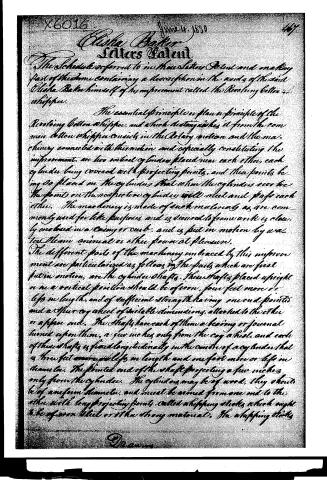
The Schedule referred to in these Letters Patent and making part of the same containing a description in the words of the said Elisha Baker himself of his improvement called the Revolving cotton whippers.
The essential principle or plain principle of the Revolving cotton whippers, and which distinguishes it from the common cotton whippers consists in the Rotary motion and the machinery connected with this motion and especially constituting the improvement. Are two vertical cylinders placed near each other, each cylinder being covered with projecting points, and these points being so placed on the cylinders that when the cylinders revolve the points on the respective cylinders will meet and pass each other. The machinery is made of such materials as are commonly used for like purposes and is secured to frame work is closely enclosed in a casing or curb, and is put in motion by water, steam, animal or other power at pleasure.
The different parts of the machinery embraced by this improvement are particularized as follows: The parts which are first put in motion, are the cylinder shafts. These shafts placed upright or in a vertical position should be of iron, four feet more or less in length, and of sufficient strength having one end pointed and a spur or a wheel of suitable dimensions, attached to the other or upper end. The shafts have each of them a bearing or journal turned upon them, a few inches only from the cog wheel, and each of these shafts is fixed longitudinally in the center of a cylinder that is three feet more or less in length and one foot more or less in diameter. The pointed end of the shaft projecting a few inches only from the cylinder. The cylinders may be of wood, they should be of uniform diameter, and must be armed from one end to the other with long projecting points, called whipping sticks which might be of iron steel or other strong materials. The whipping sticks
Page 3.
should be round and smooth, and they must be firmly secured by one end to the cylinders from which they may project somewhere about twelve or eighteen inches, and their direction must be horizontal or at right angles with the surface of the cylinders. There may be more or less of the whiffing sticks at pleasure in each cylinder, but when inserting these sticks care should be taken to place them in a spiral direction around the cylinder from one end to the other of it, and they must be placed at such distance from each other, as to leave around the cylinder a horizontal space rather more than equal to the size of one of the sticks. This may be accomplished by making around the cylinder fourteen, more or less, horizontal circles, at equal distances from each other, taking care that the space between the circles be rather larger than a whiffing stick; then insert a whiffing stick in every other circle on the one cylinder, and in the corresponding intermediate circles on the other cylinder, observing to place the whiffing sticks spirally, from one end to the other of the cylinder. The cylinder shafts complete with gear, cylinders, & whiffing sticks are to be stationed by the side of, parallel with, and so near to each other that the points of the whiffing sticks on the one cylinder will nearly touch the other cylinder itself. The shafts are to be kept in this position by a frame of wood or other material. The frame is composed of several pieces well secured to each other, two of which are called the upright posts. The upright posts stand perpendicularly on the floor of the building are six or eight feet high, and stationed at the proper distance, say four feet, more or less, from each other, and they are confined to each other by cross pieces which extend from the one to the other post, and these pieces are called girts. The girts are four or five in number; one is at the top end of the posts, another is at the bottom end of the posts, and the remaining two girts being the most important ones are found nearer the center of the posts.
Page 4.
X6016
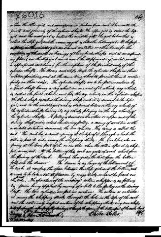
while the other girls, and correspond in distance from each other with the points and journals of the cylinder shafts. The upper girl is called the top girl, and the next girl is called the middle girl. The girl below that is called the step girl, and the remaining girl is called the bottom girl. At the top, middle, and the middle girls are secured metallic or other boxes for the reception of the needle or bearings of the cylinder shafts, and at corresponding places on the step girl are secured the steps (made of metal or other appropriate substance) for the reception of the pointed ends of the cylinder shafts. The boxes and steps keep the cylinder shafts in their relative positions, and at the same time should permit them to revolve freely on their axes. The cylinder shafts are to be put in motion by a third shaft having a cog wheel on one end of it which cog wheel is called the first wheel, and fits the cog wheels on the cylinder shafts. The third shaft is called the driving shaft, and it is secured to the top girl, and to the middle girl and is stationed between the cog wheels of the cylinder shafts having its cog wheels playing in the cog wheels of the cylinder shafts. A pulley is secured on the other or upper end of the driving shaft and is called the driving pulley, a casing of wood, tin, or other suitable substance surrounds the two cylinders. This casing is called the comb. The comb has a small opening at the top of it through which the cotton is put to enter among the whiffing sticks. The comb has also an opening at the lower part of it, on one side, when the cotton after it is whiffed comes out. At the bottom of the comb are grates of wood which form the flooring of the comb. Through these grates the dirt from the cotton falls into the drawer. The drawer is as large as the bottom end of the comb, it occupies the space between the step girl and the bottom, and is made to be taken out at pleasure by rings, knobs, or handles fixed on its side. The operation of the working cotton whiffen is as follows: by power being applied by means of a bell to the pulley on the driving shaft, the two cylinders are put in motion. The cotton is introduced among the whiffing sticks through the hole in the top of the comb and the cotton only is put in motion of the whiffing sticks very soon whiffs particles from the cotton perfectly clean, they pass through the opening at the bottom part of the comb.
The Honorable
Mary E. Stone, Author with 3
(222 words)
Christa Baker.
1866
Published accounts: journal notice
Notice in the monthly list of patents, with remarks
Journal of the Franklin Institute, new ser., vol. 6 (1830), p. 220 · View the page
6. For a "Revolving Cotton Whipper;" Elisha Baker, Warwick, Kent county, Rhode Island, June 4.
Remarks. "The essential principle, or plan, of the Revolving Cotton Whipper, and which distinguishes it from the common cotton whipper, consists in the rotary motion, and the machinery connected with this motion, and especially constituting the improvement, are two vertical cylinders placed near each other; each cylinder being covered with projecting points, and these points being so placed on the cylinders, that when the cylinders revolve the points on the respective cylinders will meet and pass each other." 1 "'The operation of the revolving cotton whipper is as follows, viz. power being applied by means of a belt to the pulley on the driving shaft, the two cylinders are put in motion. The cotton is introduced among the whipping sticks, through the hole in the top of the curb; and the extremely rapid motion of the whipping sticks very soon whips, picks, and prepares the cotton perfectly, and discharges it through the opening at the bottom of the curb." The foregoing quotations comprise the first and the last paragraphs of the specification, and afford as good a view of the structure and object of the machine as can be given without the drawing.
About this record
- Patentee
- DATAMP
- Date
- the Name and Date index of patents, DATAMP, USPTO records
- Invention
- DATAMP
- Listed in
- the Name and Date index of patents, DATAMP, USPTO records, Jim Shaw's X-patent list, the Journal of the Franklin Institute, Burke's List of Patents (1847)
- Burke's 1847 Patent Office list gives the same patent.