

Drawings and documents
National Archives restored drawings: drawing
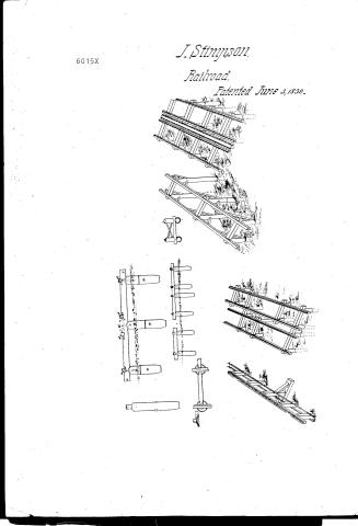
J. Stimpson's Patent Drawing for a Railroad

National Archives, Restored Patent Drawings (Record Group 241) · Full-size scan at the National Archives · Catalog record
Show the text on the drawing Hide (21 words)
Words on the drawing as machine-read by the National Archives; not checked. Useful mainly for searching.
J.Stimpson, / Railroad, / Patented June 3, 1830.
USPTO scan
The patent as scanned by the USPTO
-
 Page 1
-
 Page 2
-
 Page 3
-
 Page 4
-
 Page 5
-
 Page 6
-
 Page 7


U.S. Patent and Trademark Office · Google Patents
Show the transcription Hide (1,925 words)
Machine transcription (LightOnOCR) of the pages as scanned by the USPTO, most of them the handwritten copies made when the records were restored after the 1836 fire. Not checked; it can misread handwriting, so compare it with the scan.
Page 1.
6015X
J. Stimpson
Railroad.
Patented June 3, 1830.
Page 2.
June 3, 1830
James Simpson Baltimore Maryland
Letters-Patent
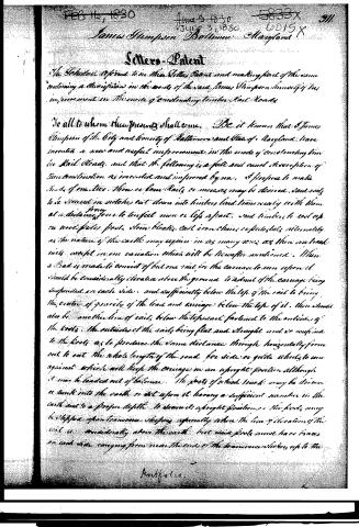
The Selective refers to in this Letters Patent and making part of the same containing a description in the words of the said James Simpson himself of his improvement in the mode of constructing timber Rail Roads.
To all to whom these presents shall come. Be it known that I James Simpson of the City and County of Baltimore and State of Maryland have invented a new and useful improvement in the mode of constructing timber Rail Roads, and that the following is a full and exact description of the construction as invented and improved by me. I propose to make roads of one line, three or four rails or more may be desired, said rails to be secured in notches cut down into timber laid transversely with them at a distance from to ten feet more or less apart, said timbers to rest on iron rods, posts, stone blocks, cast iron chains or pedestals, alternately as the nature of the earth may require in as many rows as there are track rails except in one variation which will be hereafter mentioned. When a Road is made to consist of but one rail for the carriage to run upon it should be considerably elevated above the ground to admit of the carriage being suspended on each side, and sufficiently below the top of the rail to bring the center of gravity of the load and carriage below the top of it. There should also be another line of rails below the top rail fastened to the outsides of the posts, the outsides of the rails being flat and straight and so confined to the posts as to produce the same distance through horizontally from out to out the whole length of the road for side or guide wheels to run against which will keep the carriage in an upright position although it may be loaded out of balance. The posts of which tracks may be driven a sunk into the earth or set upon it having a sufficient number in the earth and to a proper depth to secure its upright position. The posts may be stepped upon transverse sleepers especially where the line of elevation of the rail is considerably above the earth. But when posts must have bases on each side running from near the ends of the transverse sleepers up to the
Baltimore.
Page 3.
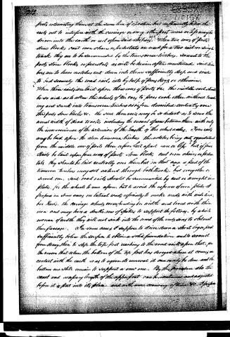
posts intersecting them at the same line of elevation, but sufficiently below the rails not to interfere with the carriage, every other post more or less may be driven into the earth or set upon said blocks. When two rows of posts, stone blocks, cast iron chains, or basket rails are used for a two rail or single track, they are to be surmounted by the transverse timbers, secured to the posts, stone blocks, or basket rails, as will be hereinafter mentioned. Said timbers are to have notches cut down into them sufficiently deep and wide to bed securely the road rails, into by help of pins, keys, or otherwise.
When three rails are laid upon three rows of posts, etc., the middle rail should be so wide as to allow the wheels of the cars to pass each other without touching and sunk into transverse timbers as before described, centrally over the posts, stone blocks, etc. The same three rails may be so distant as to cover the usual width of Road tracks, including the vacant space between them, with only the inconvenience of the extension of the length of the wheel axles. Four rails may be laid upon the above transverse timbers, the notches being cut equidistant from the middle row of posts, three or four feet apart more or less. But if four tracks be laid upon four rows of posts, stone blocks, cast iron chains, or basket rails, they should be laid centrally over themselves in that case, a part of the transverse timbers may not extend through both tracks, but over either or second one. Said road rails should be surmounted by cast or wrought iron plates, for the wheels to run upon, but to avoid the expense of iron plates, I propose in some cases on lateral roads especially to make roads with wide timber Rails. The carriage wheels corresponding in width and lined with thin iron and may have a double row of spokes to support the fellows, by which means of width they will not sink into the road of the rails, nor to obstruct their passage.
On some cases I suppose to drive down a short log or post sufficiently below the surface to obtain a solid foundation, and to secure it from decay, then to stop the tops first reaching to the road rails upon that, for the reason that when the bottom of the top post has decayed where it comes in contact with the earth, so as to require its removal, it can easily be done, and the bottom one still remain to support a new one. By this procedure, also the exact and necessary length of the uppermost can be measured and adjusted before it is put into its place, and with more economy of time, etc. I suppose
Page 4.
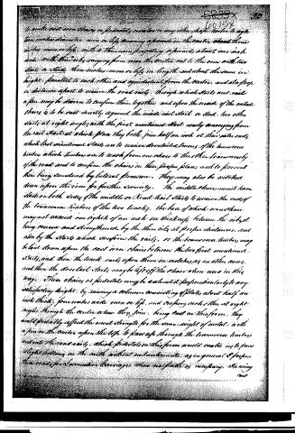
To make cast iron chairs or pedestals, cast two or any other shape timber to eight ten inches diameter iron or legs, crossing a prong in the centre about three inches iron or legs, with a thin iron projecting a prong, about one inch wide with thin irons, ranging from near the centre out to the iron with two stabs or sticks three inches iron or legs in length, and about the same in height, parallel to each other and equidistant from the centre, and at a proper distance apart to receive the road rails, through which stabs and rails a pin may be driven to confine them together, and upon the inside of the outside chairs is to be cast directly against the inside rail stabs or sticks, two other stabs at right angles with the first mentioned stabs nearly converging from the rail stabs at which place they both join half an inch at their outer ends, which last mentioned stabs are to receive dovetailed tenons of the transverse timbers which timbers are to reach from one chair to the other transversely of the road and to confine the chairs in their proper places and to prevent them being rendered by lateral pressure. They may also be notched down upon the iron for further security. The middle chair must have stabs on both sides of the middle or Road Rail stabs to receive the ends of the transverse timbers of the two tracks. The base of which iron chair may not exceed one eighth of an inch in thickness between the sides being convex and strengthened by the thin side at proper distances, and also by the stabs which confine the rails, or the transverse timbers may be laid down upon the cast iron chairs between the last first mentioned stabs, and then the track rails upon them in notches as in other cases, and then the dovetail stabs may be left off the chair when used in this way. These chairs or pedestals may be extended perpendicularly to any satisfactory height, by raising a column consisting of plates about half an inch thick, four inches wide iron or legs, and crossing each other at right angles through the centre where they join, being cast in this form, they would probably afford the most strength for the same weight of metal, with a pin in the centre upon the top to pass up through the transverse timbers and into the road rails, which pedestals in this form would enable us to pass slight hollows in the earth without embankments, as in general I propose this mode for locomotive carriages when no path is necessary. In using
Page 5.
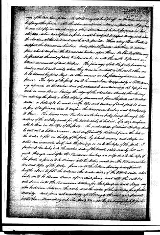
tops of the last description. The stacks may also be left off, as the timbers may be of any other form. All the above mentioned chains or pedestals, I propose to use chiefly in sand ridges, where stones cannot be well procured in hot climates, when wood posts or piles would be subject to rapid decay, and when the elevation of the road and earth will permit. When using stone blocks to support the transverse timbers, holes should be made into them to receive pins which confine the transverse timbers upon them. On blocks of stone may be placed at the ends of said timbers, ex to, or into the earth, to prevent any lateral movement of said timbers. The joinings of all the posts, transverse timbers and track sails, where they come in contact with each other are to be secured by pins, keys, or other means in the following manner and form. The tops of the posts are to be made true horizontally a little concave upwards in the centre and all reduced to a certain size at top for an inch or more down: leaving the edge of the shoulder should then be any in reducing the posts a little sloping downwards from the posts out to the water. A hole is to be made in the tops and centres of said posts to receive a pin of sufficient size to confine the transverse timbers and track sails to them. The transverse timbers are to have holes bored through the centres of the notches made for the track sails to bed in, of a size conformable to those in the tops of the posts. The under sides of which timbers shall be cut out a little concave, and sufficiently distant from the holes in the centre to fit on the tops of the posts, by which means and shape no water can inanimate itself into the joinings or on to the tops of the posts. I propose to cut holes into the under sides of the track sails, nearly but not quite through and after the transverse timbers are adjusted to the tops of the posts, a pin is to be driven into the holes made in the transverse timbers and tops of the posts, from on to the bottom leaving a sufficient length above to fill the holes in the under sides of the track sails, which sills are to be driven down upon said pins and into the notches cut down into the transverse timbers for that purpose, and keys may also be driven between the sills and the sides of the notches for a further security. Said pins not reaching up through the said sills prevent water from descending into the posts, &c. as the pins may be left just
Page 7.
346.
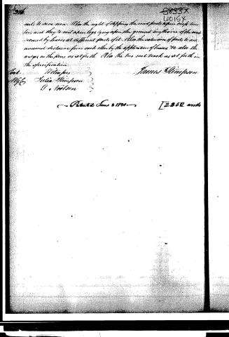
Also the right of stepping the said posts upon eight timbers, and they to rest when legs lying upon the ground by the means of the same secured by braces at different parts of it. Also the extension of posts to an unusual distance from each other by the application of braces. To also the wings in the pins as set forth. Also the two said tracks as set forth in the specification.
James Simpson
Wm. J. Simpson
Julia Simpson
H. T. Wilson
Patented June 3, 1851
[2352 words]
Published accounts: journal notice
Notice in the monthly list of patents, with remarks
Journal of the Franklin Institute, new ser., vol. 6 (1830), p. 219 · View the page
4. For a Timber Rail-road; James Stimpson, Baltimore, Maryland, June 3.
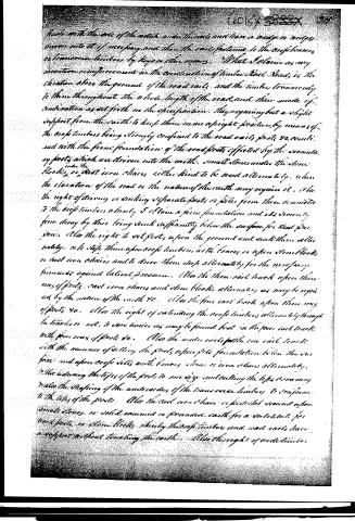
Remarks. We will begin our account of this patent with the finale of the specification, or rather of the claim. "What I claim as my invention, or improvement, in the construction of timber rail-roads, is the elevation above the ground of the road-rails, and the timbers transversely to them throughout the whole length of the road, and their mode of combination, as set forth in the specification; they requiring but a slight support from the earth to keep them in an upright position, by means of the cross timbers being strongly confined to the road-rails, posts, &c. combined with the firm foundation of the road posts, effected by the secondary posts, which are driven into the earth, small stones under the stone blocks, or under the cast iron chairs, either kind to be used alternately, when the elevation of the road, or the nature of the earth may require it. Also the right of driving or sinking separate posts, or piles, from those connected to the cross timbers, whereby I obtain a firm foundation, and its security from decay, by their being sunk sufficiently below the surface for that purpose. Also the right to set posts upon the ground, and sink them alternately, or to step them upon cross timbers with braces, or upon stone blocks, or cast iron chairs, and to drive them deep alternately, for the necessary firmness against lateral pressure. Also the three rail tracks upon three rows of posts, cast iron chairs, and stone blocks alternately, as may be required by the nature of the earth, &c. Also the four rail track, upon three rows of posts, &c. Also the right of extending the cross timbers alternately through both tracks, or not, to save timber, as may be found best, in the four rail track, with four rows of posts, &c. Also the under rails for the one rail track, with the manner of setting the posts upon pile foundations below the surface, and upon cross sills with braces, stones, or iron chairs, alternately. Also reducing the tops of the posts to one size, and cutting the tops crowning; and also the shaping of the under sides of the transverse timbers to conform to the tops of the posts. Also the cast iron chair, or pedestal, secured upon small stones, or solid rammed or pounded earth, for a substitute for wood posts, or stone blocks, whereby the cross timbers and road-rails have a support without touching the earth. Also the right of wide timber rails, to save iron. Also the right of stepping the road posts upon cross timbers, and they to rest upon logs, lying upon the ground lengthwise of the road, secured by braces at different parts of it. Also the extension of posts to an unusual distance from each other, by the application of braces, &c. Also the wedges in the pins, as set forth. Also the two rail track, as set forth in the specification." The space demanded by the claims will, we apprehend, be thought 1 quite sufficient, even by those of our readers who feel an interest in the subject of rail-roads; we, however, will add one or two remarks to render the nature of some of the claims more clear. The single rail is to be formed on the principle of one which has been patented and tried in England; the carriage is to hang on each side of the rail, the wheels being above, and in the centre between them; the lower rails spoken of are for lateral friction wheels to run against in case the two sides should be unequally loaded. In double tracks, with three rows of supports, the patentee makes the middle one of the three wooden rails, sufficiently wide for two wheels to pass each other. The wooden rails are to be covered with cast or wrought iron, or else they are to be made very wide, and the rims of the wheels also wide, to prevent their sinking into the rails. The patent in general is taken for things which are so simple and obvious that a man without the least talent at invention would resort to them because he had seen them used for other purposes every day of his life. We refer to such things as supporting an upright post by fastening it into a sill, and bracing it, and putting logs down for a sill to rest upon. If such a patent is good, no man will be left at liberty to follow the dictates of common sense, judgment, or observation, without permission from a patentee. If a post is to be used to support a rail, he will be told that he must not sink it in the ground, place its end upon an iron plate, (chair,) or upon a flat stone; that he is not to use a sill and braces, or employ timber of unusual length, or extraordinary width, as to do so is a special privilege. :
About this record
- Patentee
- DATAMP
- Date
- the Name and Date index of patents, DATAMP, USPTO records
- Invention
- DATAMP
- Listed in
- the Name and Date index of patents, DATAMP, USPTO records, Jim Shaw's X-patent list, the Journal of the Franklin Institute