

Drawings and documents
National Archives restored drawings: drawing
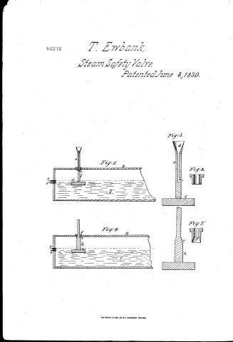
Thomas Ewbank's Patent Drawing for a Safety Valve Called "The Detector"

National Archives, Restored Patent Drawings (Record Group 241) · Full-size scan at the National Archives · Catalog record
Show the text on the drawing Hide (131 words)
Words on the drawing as machine-read by the National Archives; not checked. Useful mainly for searching.
Habety Nalves Steam Engines / 122. STEAM-BOILERS, Troms G Indicators / Indioators / Thomas Ewbank. / 750 / CLASSIFICATION / 6021-+ / Safety Valve called the Detector / Vol. Vol. 10. pg.73. / DIV ISION / Patented June8. 1830. / ol / Tig.t. / Fig.2. / Preferences. / frå / a the stuffing box. Fis. 18 2. / b. metallic 20d with its opening &. Fy3. / Fig3 / L the float / I the trumpet shaped tube. / e the graduation / f. f. gange cocks. / Fy. 4 g the value as Fig S. / h the 20d ofig. 6. / i the Conical part / K.K. the boilers. / l.l upresents the water / Jrig.5. / Tig. 4. / of / for / Patent office 31 May 1841. / Ch.L. Hischmann del / made under the direction of the Commipioner of Patents / in conformity with act of 3.ᵈ march 1837 / HL Pumpth / Commiforoner of Patents.
USPTO scan
The patent as scanned by the USPTO
-
 Page 1
-
 Page 2
-
 Page 3


U.S. Patent and Trademark Office · Google Patents
Show the transcription Hide (900 words)
Machine transcription (LightOnOCR) of the pages as scanned by the USPTO, most of them the handwritten copies made when the records were restored after the 1836 fire. Not checked; it can misread handwriting, so compare it with the scan.
Page 1.
6021X
T. Erbank,
Steam Safety Valve.
Patented June 8, 1830.
Fig. 1.
Fig. 3.
Fig. 2.
Fig. 4.
Fig. 5.
A.M. PHOTO-LITHO. CO. N.Y. (OSBORNE'S PROCESS.)
Page 2.
Thomas Ebbank
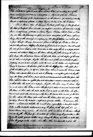
The Schedule referred to in these Letters Patent, and making part of the same, containing a description in the words of the said Thomas Ebbank himself, of his Improvement in the Machine for detecting & making known a deficiency of water in Steam Engine Boilers, called the Detector.
Be it known that I Thomas Ebbank of the City of New York, in the State of New York, have invented, an improved machine, for detecting & making known a deficiency, of water in steam Engine Boilers, which I call a Detector, and that the following is a full and exact description of the same, reference being had to the drawings accompanying this Specification, and which form a part thereof. At any convenient place on the top of a Boiler, a hole is drilled through and a stuffing box properly fixed to it, to admit a smooth metal rod, of about half an inch diameter, to slide easily thru it, in a perpendicular direction, and without letting air thru the same: the length of this rod may be about a foot longer than the distance between the top of the boiler and the surface of the water in it, when at its proper height. The lower end of this rod is attached to float properly made to rise and fall with the water in the boiler, and sufficiently heavy to overcome the friction of the rod thru the stuffing box. The upper part of the rod, that is, from its top to a little below where it enters the boiler, is made hollow, and a small hole is made into it laterally, or at right angle to its length, near the bottom of the hollow part, and so as to communicate with that part, this hole (which is about an eighth of an inch diameter) is made at such part of the rod, as that when the water is at its proper height, this hole may be about half an inch above the boiler, or above that part of it, where it comes in contact with the steam, so that when the water sinks half an inch in the boiler, the glass and rod will sink also, and consequently bring the small hole inside of the boiler; thru which the steam will rush into the hollow part and escape at top, making known by its noise a deficiency of water within. To measure this noise, a brass or iron whistle, the mouth of an organ pipe, a trumpet shaped tube, or other suitable instrument, may be fixed to the top of the rod, as circumstances may require. The diameter of the rod should be the same thruout its length. The space of an octave of boiler may be graduated, so that thru it, the eighth of water within may always be known, and that as well as when the gauge exists, as when above them. When it is necessary to avoid the
Page 3.
X6021
74
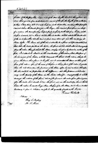
friction of the stuffing box, I use a rod of the same length, but solid throughout, and about three quarters of an inch diameter; one end of this, for the length of the orifice in the pipes, I turn down till it is only half an inch diameter, making that part of it conical where the small part joins the larger, this conical part forms one half of a valve; the corresponding half is properly fixed to the top of the boiler, with its face inward, and a hole is drilled thru its center, which admits the small end of the rod to pass thru till the conical part comes close up and thus rendering it steam tight. The lower end of the rod is attached to a float as before mentioned so that when the water sinks in the boiler, the float and rod sink also, and consequently opens the valve, through which the steam escapes, and gives, by its wise, motion of the float. It is also to be observed in the construction of this valve, that, that part of the rod inside of the boiler, which connects the float to the valve, should be of one thickness throughout its length, and its diameter the same as that of the face of the valve; for, if the area of this face or sliding part of the valve be greater than the rod diameter, the pressure of the steam upon it, not above that upon the rod, would be in proportion to the difference, and this pressure would also vary as the density of the steam in the boiler changes; consequently, it would derange the action of the float, and might prevent the valve from opening, even after the water had sunk below the float; and on the contrary, should the rod below the valve, be made larger than the face of it, the steam would have a constant tendency to open it. Whatever might be the quantity of water in the Boiler.
Thomas Eversley
Witness
Mary S. Mackay
Mr. D. B. Hunt.
1856
Published accounts: specification
Specification printed in the Journal of the Franklin Institute
Journal of the Franklin Institute, new ser., vol. 6 (1830), p. 234 · View the page
Text of the specification as printed in the Journal, from OCR; not proofread.
Specification of a patent for machinery for detecting and making known a deficiency of water in Steam Engine Boilers. Granted to THOMAS EWBANK, City of New York, June 8, 1830. Ar any convenient place on the top of a boiler, a hole is drilled through, and a stuffing box is properly fixed to it, to admit a smooth metallic rod, of about half an inch diameter, to slide easily through it in a perpendicular direction, and without letting out the steam. The length of this rod may be about a foot greater than the distance between the top of the boiler and the surface of the water in it, when at its proper height. EWBANK'S Detector for Steam Engine Boilers. The lower end of this rod is attached to a float properly made to rise and fall with the water in the boiler, and sufficiently heavy to overcome the friction of the rod through the stuffing box. The upper part of the rod, that is, from its top to a little below where it enters the boiler, is made hollow, and a small hole is made into it laterally, or at right angles to its length, near the bottom of the hollow part, and so as to communicate with that part; this hole, which is to be about one-eighth of an inch in diameter, is made at such part of the rod that when the water is at its proper height, this hole may be about half an inch above the boiler; or above that part of it where it comes in contact with the steam; so that when the water sinks half an inch in the boiler, the float and rod will sink also, and consequently bring the small hole inside of the boiler, through which the steam will rush into the hollow part, and escape at top, making known by its noise a deficiency of water within. To increase this noise, a boatswain's whistle, the mouth of an organ pipe, a trumpet shaped tube, or other suitable instrument, may be fixed to the top of the rod, as circumstances may require. The diameter of the rod should be the same throughout its length. The part of the rod outside of the boiler may be graduated, so that by it the depth of water within may be always known; and that as well when it is below the gauge cocks as when it is above them. When it is desirable to avoid the friction of the stuffing box, I use a rod of the same length, but solid throughout, and about threequarters of an inch in diameter; one end of this, for the length of ten or twelve inches, I turn down till it is only half an inch in diameter, making that part of it conical where the small part joins the larger; this conical part forms one-half of the valve, the corresponding part is properly fixed to the top of the boiler, with its face inwards, and a hole is drilled through its centre, which admits the small end of the rod to pass through, till the conical part comes up, and thus renders it steam tight. The lower end of the rod is attached to a float, as before mentioned, so that when the water sinks in the boiler, the float and rod sink also, and consequently open the valve, through which the steam then escapes, and gives, by its noise, notice of the fact. It is to be observed in the construction of this valve, that that part of the rod inside of the boiler, which connects the float to the valve, should be of one thickness throughout its length, and its diameter the same as that of the face of the valve. For if the area of the face, or closing part of the valve, be greater than the rod's diameter, the pressure of the steam upon it, over and above that upon the rod, would be in proportion to this difference; and this pressure would also vary as the density of the steam in the boiler changed; and consequently it would derange the action of the float, and might prevent the valve from opening, even after the water had sunk below the float; and, on the contrary, should the rod below the valve be made larger than the face of it, the steam would have a constant tendency to own it, whatever might be the quantity of water in the boiler. I claim as new, and as my own invention, in the above described 1 EWBANK'S Detector for Steam Engine Boilers. machine, the hollow part of the rod, with its lateral opening, or openings; also the suspending the float to the moving part of the inverted valve, by a rod of the same diameter as the face of the valve, by which means the float and valve rise and fall with the water in the boiler, uninfluenced by the steam within it. THOMAS EWBANK. Description of the Drawings. The corresponding parts in Figs. 1 and 2, are represented by the same letters. A, A, the boiler. B, B, the height at which the water ought to be kept within it. C, C, the surface of the water below its proper level, and bringing the machine into action. F, F, floats, which may be of stone, or other suitable material. The rods to which they are attached may be connected to a lever, L, and counterpoised by a weight, W, as shown in Fig. 1. R, in Fig. 1st, represents the hollow rod, passing through the stuffing boxes, with the lateral opening at O. V, the inverted valve seat, T, the tapering, or conical part of the rod, completing the valve. 0 Fig. 1. W V Fig. 2. T A B A B
Editor's remarks. It has become an object of immense public importance to devise some mode of greatly lessening, should it not be possible entirely to prevent, those fatal accidents from explosion, which have so frequently occurred, especially of late. As the public attention has been aroused to this subject, numerous plans and opinions will be presented to our consideration, and we shall deem it the wisest course to abstain, at present, from any critical remarks upon them individually, excepting in those cases where they appear to be marked with absurdity on their fronts. To others we do not prescribe the same course, but earnestly invite the most free discussion and inquiry upon a point of so much interest. In our last number, page 157, we gave a description of the plan invented and patented by Mr. Potts, for attaining the same end with the foregoing; the distinctive difference between the two, is the selfregulating action of the supply pump, which Mr. Potts aims асcomplish by the falling and rising of the float in the boiler. Mr. Ewbank is incorrect in his reasoning about the equality in the size of the rod below the valve, in his second plan; this is a point of no importance whatever; the two forces which operate, are the pressure of the atmosphere without, which will be in the proportion of its weight, and the area upon which it presses; and the elastic force of the steam within, and the area upon which it presses; the former area is the section of the rod, and the annulus of the cone, formed by the space allowed for the escape of the steam; the latter will be what is due to the elasticity of the steam, and the horizontal area of the valve seat. Any enlargement or contraction of the rod, below the valve seat, will have no more influence upon the pressure of the steam than will the area of the upper surface of the float, the pressure upon which is balanced by the pressure of the water upon its lower surface. The space contained between two circles struck from the centre of the under side of the float, the smaller of which is equal in diameter to the hole drilled through the valve seat, and the larger to the diameter of the lower part of the cone of the valve seat, will represent the area acted upon by the steam, without being counteracted by the atmosphere; from the area of the inner circle must be subtracted the pressure of the atmosphere upon an equal surface.
Published accounts: journal notice
Notice in the monthly list of patents, with remarks
Journal of the Franklin Institute, new ser., vol. 6 (1830), p. 222 · View the page
On the 23d of April, 1828, Messrs. Phillips and Mather, of Genesee county, obtained a patent similar both in its object and means, to that of Mr. Yerkley. The specification, with a cut, may be found at page 349, vol. iii. new series. In that axle, the whole of the round part of the axle, which fitted into the nave, or hub, was of cast iron, with the exception of a pin of wrought iron inserted in the end when cast, for the purpose of being cut into a screw to receive a nut, for securing the wheel. These cast iron ends are affixed to a wooden stock by hoops and bolts. In the present instance, a part only, say two-fifths, of the round part is of cast iron, so much of the wood being cut off. The wood is then sawed from top to bottom of the axle, and a piece taken out, so as to leave an opening to receive a strap, or shank, cast on to the round part, and which is to extend back into the stock of the axle-tree, and be secured in its place by hoops and bolts. The lower edge of this strap thus operates as a skein to the wooden part of the axle. A wrought pin is directed to be inserted, as in the specification of the first patent. The present patentee makes no claim, and it really appears to us that the ground occupied by Messrs. Phillips and Mather, leaves him little, or none, upon which to found one. 10. For a "DETECTOR," to make known a deficiency of Water in Steam Boilers; Thomas Ewbank, City of New York, June 8.
Remarks. (See the specification.)
Published accounts: journal notice
Notice in the monthly list of patents, with remarks
Journal of the Franklin Institute, new ser., vol. 6 (1830), p. 234 · View the page
Most articles from the spindle and the loom have of late been sold at prices so far below their intrinsic value, as nearly to banish domestic spinning and weaving from the farm house; and, of course, there has been little or no demand for machines like that above named. Whether this "Farmer's Handy Maid," is really more handy than some other maids and "Jennys" previously introduced to our acquaintance, may very fairly be doubted, as the similarity in its features indicates a great similarity of disposition and habits. These domestic spinners are generally mere epitomes of the larger machines, and such we account that under consideration. There appears to be a strong conviction of this fact in the minds of patentees, as they have rarely attempted to point out the parts which they considered as new. The same course has been adopted in the present instance, no claim being set up. Such an omission must be fatal to a patent of this description, as most of the parts of a spinning machine must be similar to those previously used. SPECIFICATIONS OF AMERICAN PATENTS. Specification of a patent for machinery for detecting and making known a deficiency of water in Steam Engine Boilers. Granted to THOMAS EWBANK, City of New York, June 8, 1830.
Remarks. Ar any convenient place on the top of a boiler, a hole is drilled through, and a stuffing box is properly fixed to it, to admit a smooth metallic rod, of about half an inch diameter, to slide easily through it in a perpendicular direction, and without letting out the steam. The length of this rod may be about a foot greater than the distance between the top of the boiler and the surface of the water in it, when at its proper height. EWBANK'S Detector for Steam Engine Boilers. The lower end of this rod is attached to a float properly made to rise and fall with the water in the boiler, and sufficiently heavy to overcome the friction of the rod through the stuffing box. The upper part of the rod, that is, from its top to a little below where it enters the boiler, is made hollow, and a small hole is made into it laterally, or at right angles to its length, near the bottom of the hollow part, and so as to communicate with that part; this hole, which is to be about one-eighth of an inch in diameter, is made at such part of the rod that when the water is at its proper height, this hole may be about half an inch above the boiler; or above that part of it where it comes in contact with the steam; so that when the water sinks half an inch in the boiler, the float and rod will sink also, and consequently bring the small hole inside of the boiler, through which the steam will rush into the hollow part, and escape at top, making known by its noise a deficiency of water within. To increase this noise, a boatswain's whistle, the mouth of an organ pipe, a trumpet shaped tube, or other suitable instrument, may be fixed to the top of the rod, as circumstances may require. The diameter of the rod should be the same throughout its length. The part of the rod outside of the boiler may be graduated, so that by it the depth of water within may be always known; and that as well when it is below the gauge cocks as when it is above them. When it is desirable to avoid the friction of the stuffing box, I use a rod of the same length, but solid throughout, and about threequarters of an inch in diameter; one end of this, for the length of ten or twelve inches, I turn down till it is only half an inch in diameter, making that part of it conical where the small part joins the larger; this conical part forms one-half of the valve, the corresponding part is properly fixed to the top of the boiler, with its face inwards, and a hole is drilled through its centre, which admits the small end of the rod to pass through, till the conical part comes up, and thus renders it steam tight. The lower end of the rod is attached to a float, as before mentioned, so that when the water sinks in the boiler, the float and rod sink also, and consequently open the valve, through which the steam then escapes, and gives, by its noise, notice of the fact. It is to be observed in the construction of this valve, that that part of the rod inside of the boiler, which connects the float to the valve, should be of one thickness throughout its length, and its diameter the same as that of the face of the valve. For if the area of the face, or closing part of the valve, be greater than the rod's diameter, the pressure of the steam upon it, over and above that upon the rod, would be in proportion to this difference; and this pressure would also vary as the density of the steam in the boiler changed; and consequently it would derange the action of the float, and might prevent the valve from opening, even after the water had sunk below the float; and, on the contrary, should the rod below the valve be made larger than the face of it, the steam would have a constant tendency to own it, whatever might be the quantity of water in the boiler. I claim as new, and as my own invention, in the above described 1 EWBANK'S Detector for Steam Engine Boilers. machine, the hollow part of the rod, with its lateral opening, or openings; also the suspending the float to the moving part of the inverted valve, by a rod of the same diameter as the face of the valve, by which means the float and valve rise and fall with the water in the boiler, uninfluenced by the steam within it. THOMAS EWBANK. Description of the Drawings. The corresponding parts in Figs. 1 and 2, are represented by the same letters. A, A, the boiler. B, B, the height at which the water ought to be kept within it. C, C, the surface of the water below its proper level, and bringing the machine into action. F, F, floats, which may be of stone, or other suitable material. The rods to which they are attached may be connected to a lever, L, and counterpoised by a weight, W, as shown in Fig. 1. R, in Fig. 1st, represents the hollow rod, passing through the stuffing boxes, with the lateral opening at O. V, the inverted valve seat, T, the tapering, or conical part of the rod, completing the valve. 0 Fig. 1. W V Fig. 2. T A B A B Remarks by the Editor.-It has become an object of immense public importance to devise some mode of greatly lessening, should it not be possible entirely to prevent, those fatal accidents from explosion, which have so frequently occurred, especially of late. As the public attention has been aroused to this subject, numerous plans and opinions will be presented to our consideration, and we shall deem it the wisest course to abstain, at present, from any critical remarks upon them individually, excepting in those cases where they appear to be marked with absurdity on their fronts. To others we do not prescribe the same course, but earnestly invite the most free discussion and inquiry upon a point of so much interest. In our last number, page 157, we gave a description of the plan invented and patented by Mr. Potts, for attaining the same end with the foregoing; the distinctive difference between the two, is the selfregulating action of the supply pump, which Mr. Potts aims асcomplish by the falling and rising of the float in the boiler. Mr. Ewbank is incorrect in his reasoning about the equality in the size of the rod below the valve, in his second plan; this is a point of no importance whatever; the two forces which operate, are the pressure of the atmosphere without, which will be in the proportion of its weight, and the area upon which it presses; and the elastic force of the steam within, and the area upon which it presses; the former area is the section of the rod, and the annulus of the cone, formed by the space allowed for the escape of the steam; the latter will be what is due to the elasticity of the steam, and the horizontal area of the valve seat.
About this record
- Patentee
- DATAMP
- Date
- the Name and Date index of patents, DATAMP, USPTO records
- Invention
- DATAMP
- Listed in
- the Name and Date index of patents, DATAMP, USPTO records, Jim Shaw's X-patent list, the Journal of the Franklin Institute, Burke's List of Patents (1847)
- Burke's 1847 Patent Office list gives the same patent.