

Drawings and documents
National Archives restored drawings: drawing
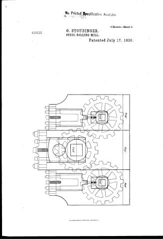
George Stoudinger's Patent Drawing for a Steel Rolling Mill


National Archives, Restored Patent Drawings (Record Group 241) · Full-size scan at the National Archives · Catalog record
Show the text on the drawing Hide (264 words)
Words on the drawing as machine-read by the National Archives; not checked. Useful mainly for searching.
Sheet 1. EORGE STOUDINGER'S / 2 sheels / STEEL ROLLING MILL. / Scale, one quarter to the inch. / CLASSIFICATION / 6083. X / for Camags S ge / Patented 17th July. 1830. / DIVISION / Cog-wheels Nos 1.&2; / one and a quarter inches thre ugh / the hole. Acrofs the cog, one inch. / Cog-wheel, N.°3; / one and a half inches through the / hole. Aorofs the cog, one inch. / The outside frames are both / to be one inch thick at each end. / N.° 3. / In the centre, one to be an inch / and a half; the other an inch / and three quarters; the projections / all come on the inside of the / frames. / N°4 Projects on the inside / of the frames, with three bolt / holes in it. / N.°1. / N°2. / George Stoudinger. / N.°4. / N.°4. / N°4. / oB
Sheet 2. HORGE STOUDIN R'S / STEEL ROLLING MILL / one quarter to the inch. / Patented 17th July, 1830. / 6083-x X / No. 12 & 13. / DIVISION. / N°.18. / N°.19. / Nos 3 & 4. / No. N°21. 21. / N°.19. / N.° 2. / with square gr / Four frames i / three quarters of / Two Rollers, like / with three grooves turned " / N°688. / Two Rollers, like No.s vss 1 127 / three grooves in them; ; and the / / end is a screw, on which is to / fastened a moveable cag-wheel. / N.° 1 / Two Shafts, like No. 10 &L & / which a screw is out, to fasten / moveable cog-wheel, to drive the / pendicular rollers. / Two Cog-wheels, like N° 18. to / on shafts No.. 10 & 11 / Two Cog-wheels, wheels, like №19. to d'a / the perpendicular rollers / Two Nuts, like N.° 21 / No. 10 & 11. / Two Nuts, like No 23. / Round and square nuts g / -ther
USPTO scan
The patent as scanned by the USPTO
-
 Page 1
-
 Page 2
-
 Page 3
-
 Page 4


U.S. Patent and Trademark Office · Google Patents
Show the transcription Hide (679 words)
Machine transcription (LightOnOCR) of the pages as scanned by the USPTO, most of them the handwritten copies made when the records were restored after the 1836 fire. Not checked; it can misread handwriting, so compare it with the scan.
Page 1.
6083X
G. STOUDINGER.
Rolling Metal Bars.
2 Sheets—Sheet 1.
Patented July 17, 1830.
N. PETERS, Photo-Lithographer, Washington, D.C.
Page 2.
No Printed Specification Available
6083X
G. SToudinger.
STEEL ROLLING MILL.
Patented July 17, 1830.
2 Sheets—Sheet 2.
![Diagram of a steel rolling mill with three gears labeled No. 1, No. 2, and No. 3, each connected to a cylindrical component with bolts and a central shaft. The gears are arranged vertically, with the top gear labeled "No. 1," the middle gear labeled "No. 2," and the bottom gear labeled "No. 3." Each gear is connected to a cylindrical component with bolts and a central shaft. The diagram is enclosed in a rectangular border with the labels "No. 1," "No. 2," and "No. 3" on the right side corresponding to each gear.]
THE MORRIS PETERS CO., PHOTO-LITHO., WASHINGTON, D.C.
Page 3.
July 17, 1830
George Stroudinger, Newark et al.
Letters Patent. X6083
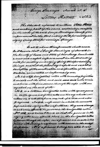
The schedule referred to in these Letters Patent and making part of the same, containing a description in the words of the said George Stroudinger himself, of his improvement in the steel rolling mill, for midling and edging spring steel for carriage springs.
To all to whom these presents shall come. Be it known that I, George Stroudinger of Newark in the County of Essex and State of New Jersey, have invented a new and useful improvement in the steel rolling mill for midling and edging spring steel for carriage springs, and that the following is a full and exact description of the construction and operation of the said Machine, as invented or improved by me.
No. 1, is a top horizontal roller with rounding projections to middle out the steel, and said, and said roller to raise and lower with four screws through the caps, with one cog wheel on the end of it.
No. 2, is a bottom horizontal roller with square grooves in, on the square end of this roller are two cog wheels; said rollers are to hold steel from one inch up to three and a half if required. Also No. 3, are frames in which the moveable perpendicular edging rollers are fastened; they move sideways so as to come opposite the grooves in the horizontal rollers No. 1, 2, and raise & lower so that the grooves in the edging rollers come opposite those in the horizontal rollers by grooves through the caps; said frames are made in two pieces with sliding brass boxes, with screws in the ends of the frames. No. 4, 5, in frames belong to other boxes to
Page 4.
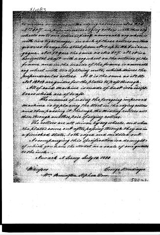
to widen or narrow the edges of the rollers in the 3rd. No. 87 are perpendicular edging rollers with heavy wheels on to one roller is fixed a movable cog wheel with two tightening nuts, in each of these rollers are two grooves to edge the steel from No. 1 up to No. 6 in a row gauge. No. 88 are the same as No. 87. No. 10 is a horizontal shaft with a cog wheel on the outside of the frame and in the inside of the frame is a movable cog wheel with two tightening nuts, which drives the perpendicular rollers. No. 11 is the same as No. 10. No. 12 & 13 are guides for the plates to pass through.
All of said machine is made of cast iron except boxes which are of brass.
The manner of using the foregoing improved machine is by placing the steel in the edging rollers and then passing it through the milling rollers and then through another pair of edging rollers.
The rollers are all driven by cog wheels, and when the plates come out after passing through they are in a finished state, both edged and milled out.
Accompanying this specification is a draught of which you have the model in a scale of one quarter to the inch.
Newark N. Jersey July 20, 1838
Witnesses
George Standing
Mrs. Bannington, Stephen Dow
520 k. 4.
Published accounts: journal notice
Notice in the monthly list of patents, with remarks
Journal of the Franklin Institute, new ser., vol. 6 (1830), p. 300 · View the page
28. For an improvement in the Rolling Mill, for Middling and Edging Spring Steel for Carriage Springs; George Stoudinger, Newark, New Jersey, July 17.
Remarks. The rollers of this mill are so formed as to edge the steel and to shape the middle in the way required for carriage springs. In the principle of the machinery there is not the slightest novelty. We do not know that carriage springs have been prepared in this way; but an almost infinite variety of other articles have been so formed. The only claim, therefore, that could be made in the present instance, would be to the particular application of it to springs; a claim of doubtful validity, and not made by the patentee.
About this record
- Patentee
- DATAMP
- Date
- the Name and Date index of patents, DATAMP, USPTO records
- Invention
- DATAMP
- Listed in
- the Name and Date index of patents, DATAMP, USPTO records, Jim Shaw's X-patent list, the Journal of the Franklin Institute, Burke's List of Patents (1847)
- Burke's 1847 Patent Office list gives the same patent.