

Drawings and documents
National Archives restored drawings: drawing
Charles Richmond and Samuel Caswell, Jr.'s Patent Drawing for Manufacturing Shovels and Spades

National Archives, Restored Patent Drawings (Record Group 241) · Full-size scan at the National Archives · Catalog record
Show the text on the drawing Hide (349 words)
Words on the drawing as machine-read by the National Archives; not checked. Useful mainly for searching.
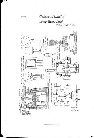
and / Shovels. / a,a, Vertical standards of Cutting Pref." / " Punch, forming the plate the shoul or / Bent or cd m driving.shaft of Culting Preze / attache In the platen in the Culting Prejs / Deprefring beam or pitman dep ending / Charles Rich monol's Samud Caswell Tris Machinery for Manufacturing Shore Is & Spades. / k.k. Die for forming plates shovel arspal / from camshaft at nnected to the / arranged in the Cutting Prefs / Punch Platen / 1,1,7,1, Guide blocks for halding the various die pm / ff Guide beams with rouves), for / CLASSIFICATION / Patente 7. april / m/m,m,7c Confining Screms passing through the bla / 8'8' Cuiding tongrues which fit into the groutes / 6460-X / 11 ye into the dieframes / ofthe guide heams / n,n n tc Knives arcultingsedges arranged / hhh Screms for confining 0 the tongrus 2:8' in / DIVISION / the interior of The vartous dies and the exter / the standards. a. / of the various punches. / so / Top View of Die-for / Rottorn Wewoflu nch / Top viewofDie for forming / Bottom view of the Punch for forming / Topview of Die for forming / Bottom view of Punch for / forming the Strap / for forming the Strap. / the Plate of the ShavetorSpade. / the Plate of the Shavel or.spade / Holes in the "Strap" / forming Holes in the Strap. / Is / Samuel / Witnefses / Same / Helen at Richmond / 11. / he / Front Elevation of / Transverse Vertical Section / Culting Press. / bangitudinal Vertical Section of / Cutting Press. / Cutting / Press. / Planortop viewof / 3. / Cutting Press / /2 / io / XIIIIA / 19 / 7. / ie / Stateof HafachuseNs. / County of Bristol ebman / 1842 / Personally appeared beforeme Charles Richmond Samuel Casrell Jr both of Taunton in the State achus Its / and made solemn oath that they are the inventors of EW and useful improvement in the mode of manufacty / by means of machinery: for which Letters Patent The United States were granted In them and the / seventh dayo) April 1831. and that the above drawing's are asthey verily believe atrue delineation ofthe / invention described in the said Letters Patint. Ilemes P.ollis. Justingth Peace / Drawn in office of R H Eddy Boston,
USPTO scan
The patent as scanned by the USPTO
-
 Page 1
-
 Page 2
-
 Page 3


U.S. Patent and Trademark Office · Google Patents
Show the transcription Hide (659 words)
Machine transcription (LightOnOCR) of the pages as scanned by the USPTO, most of them the handwritten copies made when the records were restored after the 1836 fire. Not checked; it can misread handwriting, so compare it with the scan.
Page 1.
6460X
Richmond & Caswell, Jr.
Making Hoes and Shovels.
Patented Apr. 7, 1831.
Top view of Die for forming Holes in the Strap.
Top view of Die for forming the Plate of the Shovel or Spade.
Bottom view of the Plate of the Shovel or Spade.
Bottom view of the Punch for forming the Plate of the Shovel or Spade.
Transverse Vertical Section Cutting Press.
Bottom view of Punch for forming Holes in the Strap.
Plan or top view of Cutting Press.
Bottom View of Punch for forming the Strap.
Front Elevation of Cutting Press.
Transverse Vertical Section of Cutting Press.
Witnesses
James J. Richmond.
William A. Richmond.
Inventor
Richmond
Page 2.
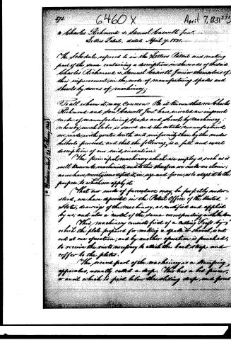
272 6460 X April 7, 1831
Charles Richmond & Samuel Basswell Junr.
Letters Patent, dated April 7, 1831.
The Schedule referred to in the Letters Patent and making part of the same, containing a description in the words of the said Charles Richmond & Samuel Basswell Junr themselves of their improvement in the mode of manufacturing spades and shovels by means of machinery.
To all whom it may concern: Be it known that we Charles Richmond and Samuel Basswell Junr have invented an improved mode of manufacturing spades and shovels by machinery; whereby much labor is saved and the articles manufactured are made with greater truth and uniformity than by the modes hitherto pursued; and that the following is a full and exact description of our said invention.
The principal machinery which we employ is such as is well known to machinists, and to this therefore we make no claim; as we have merely modified it, in size and form, as to adapt it to the purpose to which we apply it.
That our mode of procedure may be perfectly understood, we have deposited in the Patent Office of the United States, drawings of the machinery, as modified and applied by us; and also a model of the same corresponding with the same.
This machinery consists first of a cutting Press by which the plate prepared for making a spade or shovel, is cut out at one operation; and by another operation is punched, to receive the rivets necessary to attach the back strap and cover to the plates.
The second part of the machinery is a stamping apparatus, usually called a die. This has a die frame, or anvil which is fixed below the sliding stamp, and forms
Page 3.
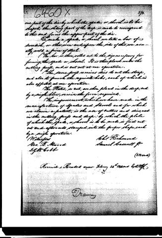
one part of the die by which the spade, or shovel is to be shaped; the sliding part of the die is made to correspond to this and forms the upper part of the die.
To make a spade, or shovel we take a bar of Swedish, or other iron and upon the side of this we usually weld a piece of steel.
The bar is then rolled out to the size necessary for forming the spade or shovel. It is then placed under the cutting press, and is cut out at one operation.
The same press receives dies to cut the strap, and also to punch the requisite holes, each of which is also effected at one operation.
The Plates, so cut, are then placed in the drop, and by a single blow, receive the form required.
The improvement which we have made in the manufacture of spades and shovels and for which we claim a patent, is the use of cutters and dies, used in the cutting press and drop; by which the plate of which the spade, or shovel is to be made is first cut out and afterwards stamped into the proper shape each by a single operation.
Witnesses
Geo. B. Mawood
D.G. M. Cobb
John Richmond
Samuel Coatswell Jr.
(512 words)
Received & Recorded anew February 24th 1822 and E. M. H.
Drawing
Published accounts: journal notice
Notice in the monthly list of patents, with remarks
Journal of the Franklin Institute, new ser., vol. 8 (1831), p. 113 · View the page
18. For manufacturing Spades and Shovels by means of machinery; Charles Richmond and Samuel Caswell, Jr., Taunton, Bristol county, Massachusetts, April 7.
Remarks. (See the specification.)
Published accounts: journal notice
Notice in the monthly list of patents, with remarks
Journal of the Franklin Institute, new ser., vol. 8 (1831), p. 129 · View the page
The second part of the machinery is a stamping apparatus, usually called a drop. This has a bed piece, or anvil, which is fixed below the sliding drop, and forms one part of the die by which the spade, or shovel, is to be shaped; the sliding part of the drop is made to correspond to this, and forms the upper part of the die. To make a spade, or shovel, we take a bar of Swedish, or other, iron, and upon the side of this we usually weld a piece of steel. The bar is then rolled out to the size necessary for forming the spade, or shovel. It is then placed under the cutting press, and is cut out at one operation. The same press receives dies to cut the strap, and also to punch the requisite holes, each of which is also effected at one operation. The plates, so cut, are then placed in the drop, and by a single blow receive the form required. The improvement which we have made in the manufacture of spades and shovels, and for which we claim a patent, is the use of cutters and dies, used in the cutting press and drop, by which the plate of which the spade, or shovel, is to be made, is first cut out, and afterwards stamped into the proper shape, each by a single operation. CHARLES RICHMOND. SAMUEL CASWELL, JR. Specification of a patent for an improvement in the Standing Press, which the patentee denominates the Inclined Plane Friction Roller Press. Granted to LUTHER CARMAN, Oxford, Oxford county, Maine, April 7th, 1831.
Remarks. To all whom it may concern, be it known, that I, Luther Carman, of Oxford, in the county of Oxford, and state of Maine, have invented an improved press, applicable to a great variety of purposes, which press I denominate the Inclined Plane Friction Roller Press; and that the following is a full and exact description of the same. VOL. VIII.-No. 2.-AUGUST, 1831. 17 CARMAN'S Inclined Plane Friction Roller Press. I construct a frame of wood, or iron, in the ordinary form of frames for presses. That is, having cheeks, or uprights, with a bed piece, or sill, and a cap piece strongly framed into, or otherwise attached to, them. Between the cap piece and bed, a third piece is framed, or attached to the cheeks in the same manner. This third piece may be much smaller than the other two, as it merely operates as a guide and support to the other parts, but does not sustain any of the force of reaction from pressure. The pressing power is derived from the action of friction rollers against an inclined curved surface, which is effected in the following manner. A strong iron shaft has its gudgeons fitted into holes in the cap piece, and the intermediate piece above named. The lower gudgeon passes through this latter piece, as it is by its descent that the pressure is exerted. The upper gudgeon has sufficient play in the cap piece to allow it to ascend and descend the distance required. A wheel, having a wide rim, is attached to this shaft. The upper edge of the rim of this wheel has two scallops, or indentations, made in it, which correspond exactly with each other, and are made of such depth and inclination as may suit the purpose to which the press is to be applied. Two strong friction rollers are attached to the under side of the cap piece of the press; their faces being in contact with the upper rim of the wheel. The wheel is borne up by means of springs, or weighted levers, or by a rope passing over a pulley, carrying a weight sufficient to counteract that of the wheel and axle. When this wheel is turned by means of a lever, the friction rollers acting upon the indentation on its rim, will cause it to descend either rapidly or slowly, and with a varying degree of speed, or force, depending upon the degree and form of the inclination in the indented parts of the rim. The two rollers, acting at points diametrically opposite, prevent all strain upon the wheel. Where great power is required, cogs are placed around this main wheel, and a pinion with any number of teeth, is employed to turn it; a lever being applied to the shaft, or axle of such pinion.
Published accounts: specification
Specification printed in the Journal of the Franklin Institute
Journal of the Franklin Institute, new ser., vol. 8 (1831), p. 128 · View the page
Text of the specification as printed in the Journal, from OCR; not proofread.
Specification of a patent for an improved mode of manufacturing Spades and Shovels, by means of Machinery.-Granted to CHARLES RICHMOND and SAMUEL CASWELL, JR., Taunton, Bristol county, Massachusetts, April 7, 1831. To all whom it may concern, be it known that we, Charles Richmond and Saml. Caswell, Jr. have invented an improved mode of CARMAN'S Inclined Plane Friction Roller Press. manufacturing spades and shovels by machinery; whereby much labour is saved, and the articles manufactured are made with greater truth and uniformity than by the modes hitherto pursued, and that the following is a full and exact description of our said invention. The principal machinery which we employ is such as is well known to machinists; and to this, therefore, we make no claim, as we have merely so modified it, in size and form, as to adapt it to the purpose to which we apply it. That our mode of procedure may be perfectly understood, we have deposited in the Patent Office of the United States, drawings of the machinery, as modified and applied by us, and also a model of the same, corresponding with the drawings. This machinery consists, first, of a cutting press, by which the plate prepared for making a spade, or a shovel, is cut out at one operation; and by another operation is punched, to receive the rivets necessary to attach the back strap and coffer, to the plates. The second part of the machinery is a stamping apparatus, usually called a drop. This has a bed piece, or anvil, which is fixed below the sliding drop, and forms one part of the die by which the spade, or shovel, is to be shaped; the sliding part of the drop is made to correspond to this, and forms the upper part of the die. To make a spade, or shovel, we take a bar of Swedish, or other, iron, and upon the side of this we usually weld a piece of steel. The bar is then rolled out to the size necessary for forming the spade, or shovel. It is then placed under the cutting press, and is cut out at one operation. The same press receives dies to cut the strap, and also to punch the requisite holes, each of which is also effected at one operation. The plates, so cut, are then placed in the drop, and by a single blow receive the form required. The improvement which we have made in the manufacture of spades and shovels, and for which we claim a patent, is the use of cutters and dies, used in the cutting press and drop, by which the plate of which the spade, or shovel, is to be made, is first cut out, and afterwards stamped into the proper shape, each by a single operation. CHARLES RICHMOND. SAMUEL CASWELL, JR.
About this record
- Patentee
- DATAMP
- Date
- the Name and Date index of patents, DATAMP, USPTO records
- Invention
- DATAMP
- Listed in
- the Name and Date index of patents, DATAMP, USPTO records, Jim Shaw's X-patent list, the Journal of the Franklin Institute, Burke's List of Patents (1847), the Journal of the Franklin Institute, Journal
- Burke's 1847 Patent Office list gives the same patent.