

Drawings and documents
National Archives restored drawings: drawing
David Anthony's Patent Drawing for a Machine for Making Horeshoes

National Archives, Restored Patent Drawings (Record Group 241) · Full-size scan at the National Archives · Catalog record
Show the text on the drawing Hide (103 words)
Words on the drawing as machine-read by the National Archives; not checked. Useful mainly for searching.
59. Chains.Staples & Horseshoes, / Horsesshoe Machines- / Jaw or former, rotary. / Lavid Anthony / CLASSIFICATION / 6461-+ / DIVISION. / Machine for making Howe Shoes / Patenter Aprils 1831 / O. / L. / us / Preferences / A Trame / E Wheels to shapes Countersink the iron. / C Horizontal wheel, Rollers, Cams de / D Irregular horizontal wheel / E. F bhivels Irvover & pieces of steel letinto them / M Cam at the end of lever / G Patterns / N. arms. / H Levers / O Bevel gearing / Springs / P Picce of iron tabe formed ints / I Cams / shoes. / K Rollers. / L Horizontal Roller.
USPTO scan
The patent as scanned by the USPTO
-
 Page 1
-
 Page 2
-
 Page 3
-
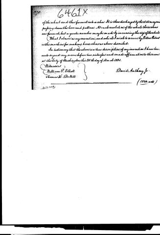 Page 4


U.S. Patent and Trademark Office · Google Patents
Show the transcription Hide (1,077 words)
Machine transcription (LightOnOCR) of the pages as scanned by the USPTO, most of them the handwritten copies made when the records were restored after the 1836 fire. Not checked; it can misread handwriting, so compare it with the scan.
Page 1.
6461X
D. Anthony.
Horse Shoe Machine.
Patented Apr. 8, 1831.
Page 2.
6461X April 8, 1831
David Anthony Jr. & Adams, Massachusetts.
Letters Patent.
Dated April 8th 1831.
The Schedule referred to in these Letters Patent and making part of the same containing a description in the words of the said David Anthony Jr. himself of his improvement being a machine for making horse shoes.
Be it known that I, David Anthony Jr. of the Town of Adams in the County of Berkshire and State of Massachusetts, have made a new and useful improvement, being a machine for making Horse Shoes, which is described as follows:
This machine consists of three principal parts: 1. The Frame. 2. The Wheels to shape and countersink the iron for the shoe. 3. The horizontal wheel, rollers, cams, etc. to form the shoe.
Its operation is somewhat similar to the common Rolling mills for plating iron.
1. The Frame. This is of iron about three feet long, three feet wide, and two feet six inches high.
2. The wheels to shape and countersink the iron for the shoe. Within the above mentioned frame, and near one end of it, are placed four iron wheels about fourteen inches in diameter, and two inches in thickness, two of which run horizontally and two vertically, with their peripheries so far apart as to leave a space equal to the size of the piece of iron intended for the shoe. Each wheel has an axle where a gear pinion is to be placed in the frame; and the edges of each wheel are bevelled. One of the horizontal wheels has its circumference divided into three equal parts and each part shaped in the form of a segment of a larger circle than the wheel, in order to give a proper taper to the piece of iron for the shoe. The upper vertical wheel has six grooves at equal distances apart on its circumference; into each of which grooves is let a piece of steel or cast iron, projecting about an eighth of an inch; this piece of steel or cast iron, forms the material on the under side of the shoe for the heads of the nails. There are also on the inner circumference of this wheel, three chisels placed at equal distances apart to cut the bar of iron into proper lengths for the shoes as it advances between the wheels, or the chisels may be placed at unequal distances apart for different sized shoes. The wheels are geared together and made to revolve equally, by means of wheels or bevel gearing on their axles, meshing into each other.
Page 3.
3. The horizontal wheel, Rollers, cams, &c. to form the shoe.
This wheel is of iron twenty eight inches in diameter, one inch in thickness, turning horizontally on an axle whose gudgeons turn in brass boxes, in the upper and lower cross pieces of the frame; its periphery revolves near where the four wheels above described come together, and polish the iron, when prepared for shaping into shoes leaves them. The rim of this wheel has three spaces left in it at equal distances apart, each space being sufficiently large to admit the pattern hereafter to be described to rise and fall when necessary. From the axle or shaft of this wheel projects about an inch a small piece of iron to which is attached by a joint or hinge a lever, on the end of which there is secured the pattern around which is formed the shoe: the lever with the pattern is held up to its place by a spring resting on an arm projecting from the axle or shaft below the lever. On the upper surface of the rim of the wheel are cams to guide the rollers hereafter to be described. To the upper part of the frame are attached two iron rollers, which with the aid of the pattern and cams form the shoe. The rollers turn horizontally and are allowed to move laterally in a mortice in the frame sufficiently large to receive them. Another roller is placed across the rim of the wheel, between, or just behind the rollers last mentioned and serves to keep the piece of iron in its place while bending. To the frame, a few inches beyond the rollers, is attached a cam, which as the wheel revolves, comes in contact with the end of the lever, presses it down with the pattern, and leaves the shoe discharged, and the pattern ready to receive another. There are two other levers and patterns besides the one just described, and similar to it attached to the above mentioned axle. This horizontal wheel is geared to the four wheels first described by mitre cog wheels or bevel gearing, and is turned at the same time and by the same power that turns them.
For a further illustration of this machine reference must be had to the annexed drawings of the same forming part of this specification.
Operation. The machine being put in motion by water or steam power, and the bar of iron heated to a red heat, the end of the bar is passed into the space formed by the peripheries of the four wheels coming nearly together and tapped, consequently, and cut into proper lengths for the shoes by the revolution of the wheels; each piece cut after this operation, and as it leaves the four wheels is received by the horizontal wheel between the rollers and pattern, but round the latter by the revolution
Page 4.
of the wheel and thus formed into a shoe. It is then discharged by the steam engine, pressing down the lever and pattern. At each revolution of the wheel three shoes are formed, but a greater number may be made by increasing the size of the wheel.
(What I claim as my invention, and which I wish to secure by Letters Patent is the machine for making horse shoes as above described.
In testimony that the above is a true description of my invention I have hereunto signed my name before two witnesses and made affirmation to the same at the City of Washington this 25th day of March 1831.
Witnesses:
William P. Elliott
Thomas H. DeMille
David Anthony Jr.
(1032-ads)
Published accounts: journal notice
Notice in the monthly list of patents, with remarks
Journal of the Franklin Institute, new ser., vol. 8 (1831), p. 114 · View the page
22. For a Machine for making Horse Shoes; David Anthony, Jr., Adams, Berkshire county, Massachusetts, April 8.
Remarks. The horse shoe is to be formed by means of wheels, or rollers, of which there are to be four; they are to be made narrow upon their faces. These rollers have axes, the gudgeons of which run in a strong iron frame, in the centre of which their faces meet; they stand opposite to each other, in pairs, so that a section through their axes would form a +. They are geared together by bevel wheels, and all turn simultaneously. Their edges are bevelled, to bring them in contact, and their faces are so formed that a bar of iron passed between them will assume the shape required, and be countersunk, so that when bent round, the horse shoe will be in a nearly finished state. The wheels may be of such circumference as to form three shoes at one revolution. From these rollers the iron passes on to an apparatus for bending it round in the required curve. The claim is to " the machine for making horse shoes as above described." We have no doubt that a machine of the foregoing kind, if made with great precision, will give to the iron the shape desired, but as regards the validity of the claim, the same circumstance which interferes with many new inventions, stands in the way of this; it unfortunately is old. A machine of this description was first brought into use in England, and was eventually imported into France. Of the period of its invention we are not informed, but in the Recueil Industriel, for December, 1828, published in Paris, a description and plate of this instrument may be found. It is there denominated "a machine which is to give to iron all the different forms required in the arts, by means of a continuous rotary motion." The French account remarks that by an engine of eight horse power, operating upon a machine of the size designated, 3,000 nails of an inch in length, might be manufactured in a minute; and that by its aid iron may be converted into any desired form in a very rapid and exact manner. A comparison of the patent before us, and of the accompanying drawing, with the description and engraving in the above journal, will remove all doubt with regard to the perfect identity of the two machines. The opposite sketch will afford some idea of the manner in which the wheels, or rollers, run together. Were their angular points taken off, a square bar might be formed by passing the metal between them; and other desired shapes, it is evident, might be produced, by indentations of the proper form.
About this record
- Patentee
- DATAMP
- Date
- the Name and Date index of patents, DATAMP, USPTO records
- Invention
- DATAMP
- Listed in
- the Name and Date index of patents, DATAMP, USPTO records, Jim Shaw's X-patent list, the Journal of the Franklin Institute, Burke's List of Patents (1847)
- Burke's 1847 Patent Office list gives the same patent.