

Drawings and documents
National Archives restored drawings: drawing
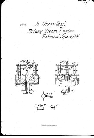
A. Greenleaf's Patent Drawing for a Rotary Steam Engine

National Archives, Restored Patent Drawings (Record Group 241) · Full-size scan at the National Archives · Catalog record
Show the text on the drawing Hide (43 words)
Words on the drawing as machine-read by the National Archives; not checked. Useful mainly for searching.
121. STEAM. / 1. / [150] Concentrio-Piston. ENGINES. Rotary. (abel) / SeA, / CLASSIFICATION / 6489-7 / DIVISION / Patented 18th April 1831. / V.12. V, N.451 / Rotary Steam Engine. / Fig.2. / Fig.1. / fy / and / 11 / 00 / Is / to / Fig.3. / Fig.4. / Fig.5;
USPTO scan
The patent as scanned by the USPTO
-
 Page 1
-
 Page 2
-
 Page 3
-
 Page 4


U.S. Patent and Trademark Office · Google Patents
Show the transcription Hide (939 words)
Machine transcription (LightOnOCR) of the pages as scanned by the USPTO, most of them the handwritten copies made when the records were restored after the 1836 fire. Not checked; it can misread handwriting, so compare it with the scan.
Page 1.
6489X
A Greenleaf,
Rotary Steam Engine.
Patented Apr. 18, 1831.
Fig. 2
Fig. 1
Fig. 3
Fig. 4
Fig. 5
Page 2.
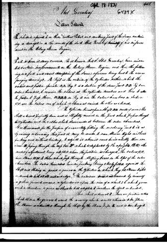
The subscriber referred to in their Letters Patent and making part of the same containing a description in the words of the said Abel Greenleaf himself of his improvement in the Rotary Steam Engine.
But when it may concern, It is known that Abel Greenleaf have issued to certain improvements in the Rotary Steam Engine and thus the following is a full and exact description of the same; reference being had to the accompanying drawings. A Fig 1 is the outline of the Cylinder within which the valves and piston operate. A A Fig 2 is a section of the same part. B B Fig 1 are valve chambers to receive the valves as the cylinder revolves and thus to allow the piston to pop them. B B B B in Fig 2 are the valve chambers in section. C C are the valves one of which is shown as raised the other as closed.
The Cylinder turns upon a shaft D D made of iron; this shaft is turned perfectly true and is slightly conical in the part which passes through the cylinder and the collar which surrounds it between the valve chambers. It is thus made for the purpose of accurately fitting the revolving part to it as by raising or lowering this part it may be made to run steam tight without packing and without binding. To adjust it when it runs loose it is only necessary to raise or lower the poppet through the orifice D which is supported by the uprights C C; other modes of adjustment being adopted when the position is changed. The valves C C have stems D D D to them which pass through stuffing boxes in the tops of the valve chambers. The valve chambers having packing being closely fitted against the shaft and sliding in guides or grooves in the cylinder in which they do steam tight or work to hold at its end and edge. The valves are raised and lowered by means of a gear formed around a cylinder or upon the rim of a wheel; to which gear such a direction is given as shall be best adapted to produce the effect intended.
This wheel is driven at E. There are friction rollers which drive the gears to avoid the wearing which would otherwise take place. The steam is admitted through the shaft by the steam pipe F and is one legged.
Page 3.
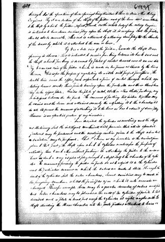
throughout the operation of these openings being similar to those in steam or other steam engines. By it is a section of the shaft of the piston and of the lever or arm which is the shaft by which the piston is first moved. As the whole body of the rotary engine is intended to have some vertical play upon the shaft it is necessary that the piston should also be movable. This end is attained by allowing some play to the threads of the screws by which it is attached to the arm or lever.
Fig 4 is a side view of the piston. Towards the shaft D an opening is shown: this is intended to receive packing between its back end and the shaft which packing is secured by plates of metal screwed over it on one side. Fig 5 is an end view of the piston which is made in two pieces as shown by the lines thereon. This is for the purpose of regulating its width with perfect precision. The fourth line near the upper part represents a piece of metal through which regulating screws work: their points bearing upon the parts D, D, and their threads bearing in the upper plate. Besides the plate of metal, cloth or other elastic packing may be interposed between the two parts. The manner of putting this piston together may be varied and the same end attained namely the adjusting it to the chamber but in all it forms the manner of attaching it to the lever or bar to admit of some play. Moreover is an essential feature of my invention.
I have described the cylinder as revolving and the shaft as stationary but the intelligent mechanic will perceive that all its essential features may be preserved and the revolving motion given to the shaft when such a variation may be preferred. That I claim as my invention is the circular form given to that part of the shaft upon which the cylinder revolves for the purpose of actuating them each other without packing; the attaching the piston to the arm or lever in such a way as to give it play enough to adapt itself to the chamber of the cylinder. The manner of forming the piston in parts etc and to adjust it to the cylinder and the particular manner in which the valves are made to slide through the head of the cylinder into the valve chambers. Several variations may be made in the foregoing machines without the principles upon which it acts remain unchanged. Thus for example there may be a greater number of valves and pistons. Valve chambers may be placed on the ends of the cylinder opposite to that described and a plate or head put across the cylinder at right angles with the shaft dividing the steam chamber into two parts pistons attached to levers etc.
Published accounts: journal notice
Notice in the monthly list of patents, with remarks
Journal of the Franklin Institute, new ser., vol. 8 (1831), p. 124 · View the page
46. For a Rotary Steam Engine; Abel Greenleaf, Paris, Oneida county, New York, April 16.
Remarks. The greater number of rotary steam engines which have been devised, differ from each other principally in the construction of, and in the manner of opening and closing the valves, and such is the case in the present instance. The description refers throughout to the drawing which accompanies it. The claim is in the following terms. "What I claim as my invention, is the conical form given to that part of the shaft upon which the cylinder revolves, for the purpose of adjusting them to each other without packing; the attaching the piston to the arm, or lever, in such way as to give it play enough to adapt itself to the chamber of the cylinder. The manner of forming the piston in parts, so as to adjust it to the cylinder; and the particular manner in which the valves are made to slide through the head of the cylinder into the valve chambers."
About this record
- Patentee
- DATAMP
- Date
- the Name and Date index of patents, DATAMP, USPTO records
- Invention
- DATAMP
- Listed in
- the Name and Date index of patents, DATAMP, USPTO records, Jim Shaw's X-patent list, the Journal of the Franklin Institute, Burke's List of Patents (1847)
- The Franklin Institute's journal gives a different date.
- Burke's 1847 Patent Office list gives the same patent.