

Drawings and documents
National Archives restored drawings: drawing
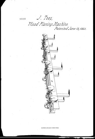
Jacob Tee's Patent Drawing for a Planing Machine

National Archives, Restored Patent Drawings (Record Group 241) · Full-size scan at the National Archives · Catalog record
Show the text on the drawing Hide (61 words)
Words on the drawing as machine-read by the National Archives; not checked. Useful mainly for searching.
#2- / 144 WOOD-WORKING MACHINES. / Planers, Sliding. / Sacob Tees Lacob Tees / CLASSIFICATION / 6609 + / Staning MachineSumber Machine / DIVISION. / Patented 13 June 1831. / Rafless / I Bench / P. Ballons / C Plane not / D Planes 720 2 / I's Planes no 3 / I' E'riction Rollers / G Drums". / H Pedestalo / L Buxes / 0 Circu Circular Saw. Saw.
USPTO scan
The patent as scanned by the USPTO
-
 Page 1
-
 Page 2
-
 Page 3
-
 Page 4
-
 Page 5


U.S. Patent and Trademark Office · Google Patents
Show the transcription Hide (1,316 words)
Machine transcription (LightOnOCR) of the pages as scanned by the USPTO, most of them the handwritten copies made when the records were restored after the 1836 fire. Not checked; it can misread handwriting, so compare it with the scan.
Page 1.
6609X
J. Tees,
Wood Planing Machine.
Patented June 13, 1831.

AM. PHOTO-LITHO. CO. N.Y. (OSBORNE'S PROCESS)
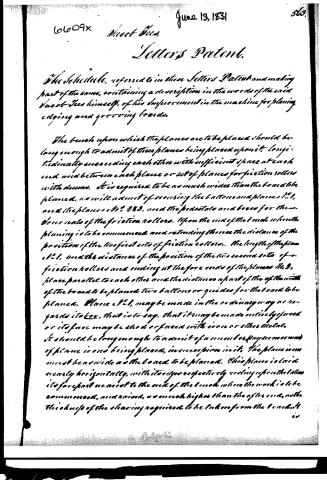
Page 2.
June 13, 1831
6609X
Sheet No. 2
Letters Patent.
The Schedule, referred to in these Letters Patent and making part of the same, containing a description in the words of the said Sheet-Teas himself, of his improvement in the machine for planing, edging and grooving boards.
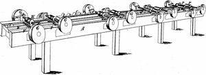
The bench upon which the planes are to be placed should be long enough to admit of three planes being placed upon it, longitudinally succeeding each other with sufficient space at each end and between each plane or set of planes for friction rollers with drums. It is required to be as much wider than the board to be planed, as will admit of securing the buttons and planes No. 1, and the planes No. 2 & 3, and the pedestals and boxes for them, over each of the friction rollers. Upon the end of the bench where the planing is to be commenced and extending thereon the distance of the position of the two first sets of friction rollers. The length of the plane No. 1, and the distance of the position of the two second sets of friction rollers and ending at the fore ends of the planes No. 2, place parallel to each other and the distance apart of the width of the board to be planed two buttons or guides for the board to be planed. Plane No. 1, may be made in the ordinary way as regards its box, that is to say, that it may be made entirely of wood or its face may be shod or faced with iron or other metal. It should be long enough to admit of a number (say two or more) of plane irons being placed, in succession in it. The plane iron must be as wide as the board to be planed. This plane is laid nearly horizontally, with its edge respectively resting upon the buttons its fore part nearest to the end of the bench where the work is to be commenced, and raised, as much higher than the other end, as the thickness of the shaving required to be taken off from the board. It
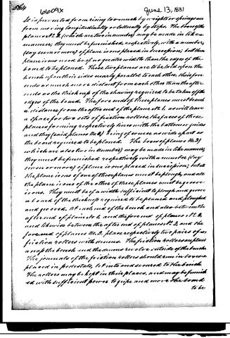
Page 3.
It is prevented from rising too much by weights or springs and from moving longitudinally or laterally by stops. The boxes of the planes No. 2, 3, (which are two in number) may be made in like manner; they must be furnished, respectively, with a number (say seven or more) of plane irons placed in succession; but the plane irons need be of no greater width than the edges of the board to be planed. These two planes are to be laid upon the bench upon their sides nearly parallel to each other, their fore ends no much more distant from each other than the after ends as the thickness of the shaving required to be taken off the edges of the board. The fore ends of these planes must bench a distance from the after end of the plane No. 1, as will leave a space for two sets of friction rollers, the faces of these planes forming respectively lines with the bottom or guides and they (said planes No. 2, 3) being of course as wide apart as the board required to be planed. The boxes of planes No. 3, (which are also two in number) may be made in like manner; they must be furnished respectively with a number (say seven or more) of plane irons placed in succession; but the plane irons of one of these planes must be plough, and all the plane irons of the other of these planes must be groove irons. They must be of a width sufficient to plough and groove a board of the thickness required to be planed and ploughed and grooved. At each end of the bench and also between the after end of plane No. 1, and the fore end of planes No. 2, and likewise between the after end of planes No. 2, and the fore end of planes No. 3, place respectively two pairs of friction rollers with screws. The friction rollers are placed across the bench and the drums revolve outside of the bench. The journals of the friction rollers should run in boxes, placed in pedestals, let into and secured to the bench. The rollers may be kept in their places, and may be furnished with sufficient power to guide and move the board to be
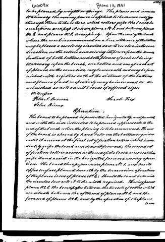
Page 4.
60609x
June 13, 1831
to be planed, by weights or springs. The planes and iron are stationary the moving power is applied to the drums and from through them to the rollers, which rollers grip the board in succession and pass it under planes No. 1, and between planes No. 2, and planes No. 3, successively. Upon the end of the bench where the work is commenced on a line with one of the buttons may be placed a revolving circular saw to revolve in the same direction as the rollers and deriving its power from the drums. Instead of both buttons and both planes of each set being stationary upon the bench, one button and one of each set of planes, on the same side, may be moveable and may be furnished with registers so that the distance of the buttons and planes of a set respectively may be increased or diminished so as to admit boards of different sizes.
Witnesses
Peter A. Browne
Jacob Lees
John Binnig.
Operation.
The board to be planed is presented horizontally, and firm, and with the side intended to be planed uppermost, to the end of the bench where the planing is to be commenced. The end of the board is shoved by hand between the buttons or guides until it arrives at the first set of friction rollers which immediately grip the board and draw it forward; the second set of friction rollers as soon as the end of the board arrives at them grip it and assist in the horizontal forward moving operation. The board thus passes under plane No. 1, and has its upper surface planed smooth by the successive operations of the planes iron of plane No. 1; should the board be too wide the circular saw cuts it to the width required. Having passed plane No. 1, the board passes between the two sets of rollers which are situated between the after end of plane No. 1, and the fore end of plane No. 2, and by the operation of the plane iron
Page 5.
June 13, 1831
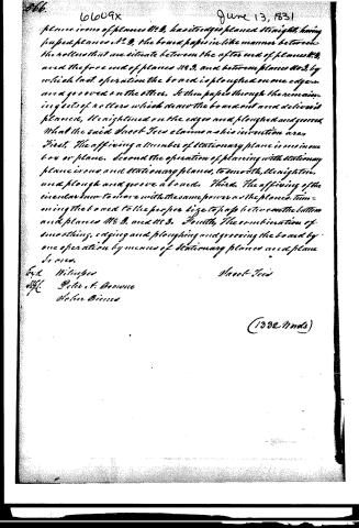
plane irons of planes No. 3, has its edges planed straight, having passed planes No. 3, the board passes in like manner between the rollers that are situated between the after end of planes No. 3, and the fore end of planes No. 3, and between planes No. 3, by which last operation the board is ploughed on one edge, and grooved on the other. It then passes through the remaining sets of rollers which draw the board out and deliver it planed, straightened on the edges and ploughed and grooved. What the said Sheet Iron claims as his invention are, First, The affixing a number of stationary plane irons in one box or plane. Second, the operation of planing with stationary plane irons and stationary planes, to smooth, straighten, and plough and groove a board. Third, The affixing of the circular iron to move with the same power as the planes, trimming the board to the proper size to pass between the bottom and planes No. 3, and No. 3. Fourth, The combination of smoothing, edging and ploughing and grooving the board by one operation by means of stationary planes and plane irons.
Exch. Witnessed
Wm. Peter T. Browne
John Binns
Sheet Iron
(1332 Words)
Published accounts: journal notice
Notice in the monthly list of patents, with remarks
Journal of the Franklin Institute, new ser., vol. 8 (1831), p. 341 · View the page
47. For a machine for Planing, Edging and Grooving Boards; Jacob Tees, Kensington, Philadelphia county, Pennsylvania, June 13.
Remarks. A bench is prepared to sustain the planes, and other apparatus required for the operation. The planes are to be stationary, and the board is to be forced against them. For this purpose the board is made to pass between friction rollers, turned by drums and straps. The first plane is to plane the surface. In its stock there are to be seven, or more, irons, all of the full width of the board to be planed. After passing this, it arrives between two other planes, similarly provided with irons, for planing its edges. Behind these it comes in contact with a pair of match planes, each with seven, or more, irons, to tongue and groove the board, which is thus finished. To reduce the board to a width, it is proposed to place a circular saw at the entering end of the bench, which saw is to be turned by the same power which gives motion to the plank. The description of the operation of this machine goes on as smoothly as the proposition of Falstaff to kill the enemy by fifties, and we err greatly in our calculations should the machine eventually prove more successful than the hero. Thirty-five plane irons, at least, and seven of them six inches wide, all acting together, will present obstacles to the motion of a yellow pine board, which the friction rollers will scarcely overcome, and if they do, they must operate as flatting mill rollers, and condense the stuff. We see many other, and formidable, objections, to this machine, which we have not space or time to present to our readers. We are also at a loss to know how the circular saw and the planes are to work upon the same plank at the same time: what is to become of the strip? When this machine goes into successful operation, we shall be glad to hear of it; we will then cry peccavi, and cheerfully send in our adhesion.
DATAMP: illustration
Illustrations from DATAMP

DATAMP (Directory of American Tool and Machinery Patents), via the Internet Archive · Archived DATAMP page
About this record
- Patentee
- DATAMP
- Date
- DATAMP, USPTO records, Burke's List of Patents (1847)
- Invention
- DATAMP
- Listed in
- the Name and Date index of patents, DATAMP, USPTO records, Jim Shaw's X-patent list, the Journal of the Franklin Institute, Burke's List of Patents (1847)
- The sources give different dates; the date shown is the one most of them agree on.
- The residence comes from the Franklin Institute's journal.
- The Franklin Institute's journal confirms the date shown.
- Burke's 1847 Patent Office list gives the same patent.