

Drawings and documents
National Archives restored drawings: drawing
Otis Tuft's Patent Drawing for a Printing Press


National Archives, Restored Patent Drawings (Record Group 241) · Full-size scan at the National Archives · Catalog record
Show the text on the drawing Hide (42 words)
Words on the drawing as machine-read by the National Archives; not checked. Useful mainly for searching.
Sheet 1. CLASSIFICATION / 6679 X / DIVISION. / OTIS TUFIS' / 101. PRINTING. / Bed & Platen Machines. / Printing Press. / Patented July 30th 1831. / #6679x / F' / 0,
Sheet 2. CLASSIFICATION DIVISION. 101. Bed PRINTING. is Machines / 9/C
USPTO scan
The patent as scanned by the USPTO
-
 Page 1
-
 Page 2
-
 Page 3
-
 Page 4
-
 Page 5
-
 Page 6


U.S. Patent and Trademark Office · Google Patents
Show the transcription Hide (1,396 words)
Machine transcription (LightOnOCR) of the pages as scanned by the USPTO, most of them the handwritten copies made when the records were restored after the 1836 fire. Not checked; it can misread handwriting, so compare it with the scan.
Page 1.
O. Tufts. Sheet 1. 2 Sheets.
Hand Printing Press.
No. 6679X
Patented Jul 30, 1831.
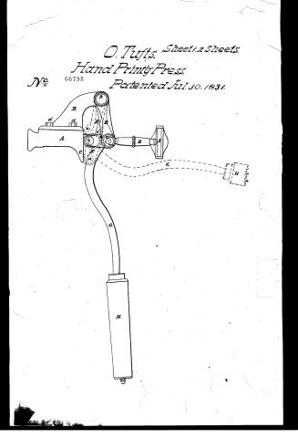
![Diagram of a hand printing press with labeled parts A, B, C, D, E, F, G, H, I, d, e, a, b, c, d, e, a, …
Page 2.
O. Tufts. Sheets 2 Sheets.
Hand Printing Press.
No 6679X Patented Jul. 30, 1831.
Page 3.
Otis Tufts
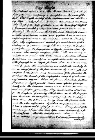
The Schedule reference to an other Patent and making part of the same containing a description in the words of the said Otis Tufts himself of his improvement in the Paving Crops. I sell persons to whom these presents shall come the Tufts of the City of Boston & in the County of Suffolk & Commonwealth of Massachusetts (Mechanician named Tufts). Be it known that I the said Otis Tufts have invented, constructed, made and applied to use a new and useful improvement in the machine called the Paving Crop. My improvement consists of a combination of machinery in a manner new & hitherto unused for the purpose of straightening the progressive or toggle jointed lever by an easy and nearly uniform pull. The machinery is simple and moves with little shank or friction. It moves the piston in nearly in a right-line with the motion of the progressive or toggle jointed lever on which it operates to give the impression, and while the working lever in every part of the pull is moved by a strength best adapted to the power and convenience of the operator, the power at the point of the impression may be of almost any desired degree. I use the frame, bed-plate, pattern, progressive or toggle jointed lever, and special springs nearly in the common manner in which the same are used in presses generally. (My combination which is for the purpose of driving the piston on the progressive lever to make it straight, employs only the working or hand lever, the piston or driving lever, the friction roller, and the other apparatus, by which the piston is made to bear & operate on the progressive lever. Every part of the machinery, I use, has been before used, separately, & for the purposes, but the combination I claim as new, to constitute my invention, & it may conveniently employed.
Page 4.
7/30/1831 6679X
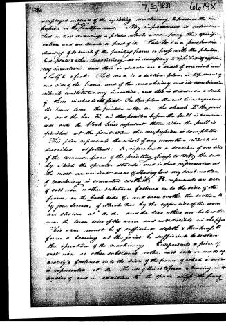
employed instead of the existing machinery to produce the impression in the friction press. My improvement is represented on two drawings or plates which accompany this specification and are made a part of it: Plate No 1 is a perspective drawing of so much of the printing frame or press with the plates, but plate & other machinery as is necessary to exhibit & explain my invention: and this is drawn on a scale of one inch and a half to a foot: Plate No 2 is a section, plan, or elevation of one side of the frame, and of the machinery and its combination which constitutes my invention, and this is drawn on a scale of three inches to the foot. In this plan the red lines represent the lines over the friction roller a, the shaft E, the joint c, and the bar D, in their position before the pull is commenced and the black lines represent them when the pull is finished at the point when the impression is completed.
This plan represents the whole of my invention which is described as follows: A, represents a section of one side of the common frame of the printing press to which the side by which the operator stands: and is thus represented as the most convenient mode of showing how my combination of machinery is connected with it. B, represents an arm of cast iron or other substance fastened on to the side of the frame, on the back side of, and even with, the section A, by four screws, of which two by the upper side of the arm are shown at a, a, and the two others are below the lower side of the arm and not visible in the figure. This arm must be of sufficient depth & thickness to form a bearing at the joint b sufficient to sustain the operation of the machinery. C represents a piece of cast iron or other substance, either cast into or made of quality & fastened on to the side of the frame of which a section is represented at A. The use of this is to form a bearing in addition of and in addition to the space over the frame.
Page 5.
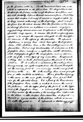
for the friction roller a... In the mechanical sense, any which is represented on the plane, since this projection is also the space for the friction roller a and the frame as a plane, and this will probably be found the most convenient form. But I have assumed that surface & it may be curved in any principle, by its being curved (either way) on the projecting part or area of the frame & in the whole sense that the friction roller traverses it may proceed on a plane or on a curve, varying in any and every desired manner as experience or the calling of the operator may require, to render the pull uniformly equal or to adapt the required strength to the best possible manner to the efforts of the operator. D represents the pitman or driving lever which bears upon the progressive lever. This pitman lever or bar has nothing more in its formation, but in any combination, it is driven on to the progressive lever nearly in a right line with its motion while it proceeds to effect the propulsion, and in this consists one of the advantages of my invention. E represents a strong bar or link proceeding from the joint b to the joint c. It is a thumb or extension of the working lever, turning nearly at right angles from the handle part of it at the moving joint b, and receiving at the end of it the friction roller a... C is the working lever made of wood or iron or other suitable substance. H is a piece that is giving or other means on the end of the working lever of a suitable size for the operator's hand. I is a part of the lower division of the progressive lever, with a socket to receive the end of the pitman. At the upper part of the piece I is the upper joint of the progressive lever. a represents the friction roller and being moved by the motion of the working lever it proceeds on the plane or other surface before described, it projects the joint c, & gives motion to the friction roller which is connected with the joint c. b represents a stationary point or
Page 6.
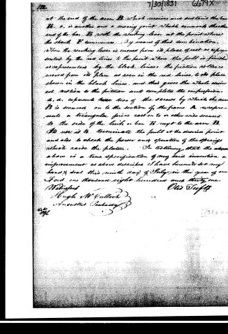
at the end of the arm B, which receives and sustains the bar B. c. is another and a moving point which connects the other end of the bar B with the working lever at the point where the shaft B' commences. By means of this combination, when the working lever is moved from its place of rest as represented by the red lines to the point where the pull is finished as represented by the black lines, the friction roller is moved from its place as seen in the red lines, to the place shown in the black lines, and thus gives the whole desired motion to the friction and completes the impression.
d. d. represents two of the screws by which the arm B is secured on to the section of the frame. A represents a triangular piece cast on to or otherwise secured to the side of the lock or bar B, next to the arm B. Its use is to terminate the pull at the desired point and also to check the power and operation of the springs which raise the platen.
In testimony that the above is a true specification of my said invention or improvement as above described, I have hereunto set my hand and seal this ninth day of July in the year of our Lord one thousand eight hundred and thirty-one.
Witnesses
Hugh W. Culloch
&
Augustus Peabody
Otis Tufts
Published accounts: journal notice
Notice in the monthly list of patents
Journal of the Franklin Institute, new ser., vol. 9 (1832), p. 63 · View the page
68. For an improvement in the Printing Press; Otis Tufts, Boston, Massachusetts, July 30.
About this record
- Patentee
- DATAMP
- Date
- the Name and Date index of patents, DATAMP, USPTO records
- Invention
- DATAMP
- Listed in
- the Name and Date index of patents, DATAMP, USPTO records, Jim Shaw's X-patent list, the Journal of the Franklin Institute, Burke's List of Patents (1847)
- Burke's 1847 Patent Office list gives the same patent.