

Drawings and documents
National Archives restored drawings: drawing
J. Wallace's Patent Drawing for a Graduating Mould for Shaping the Timbers of Vessels

National Archives, Restored Patent Drawings (Record Group 241) · Full-size scan at the National Archives · Catalog record
Show the text on the drawing Hide (76 words)
Words on the drawing as machine-read by the National Archives; not checked. Useful mainly for searching.
14. SHIPS. / 1. CONSTUCTION. / [137] Implements / J. WALLACE'S / Patented 9th Aug 1831. / CLASSIFICATION / 6693-7 / GR ADUATING MOULD FOR SHAPING THE TIMBERS OF VESSELS. / DIVISION. / Fig.1. / [#] / 012 / Fig.2. / 2. / E7 / in / Fig. / Fig.6. / Fig.4. / (a / Fig.3. / Blue pants movemble new lieus ds- / uB / hussey and the here y none, he nare / Fig.5. / A. / (6) / fool / Jostheoh muster / } $ / Fig.9. / elburn them puts / old / Fig.8. 8. / Fig.10. / miss chan gation
USPTO scan
The patent as scanned by the USPTO
-
 Page 1
-
 Page 2
-
 Page 3
-
 Page 4
-
 Page 5


U.S. Patent and Trademark Office · Google Patents
Show the transcription Hide (1,659 words)
Machine transcription (LightOnOCR) of the pages as scanned by the USPTO, most of them the handwritten copies made when the records were restored after the 1836 fire. Not checked; it can misread handwriting, so compare it with the scan.
Page 1.
No Printed Specification Available
6693X
J. Wallace.
Ship's Implement.
Patented Aug. 9, 1831.
Page 2.
6693 X
Aug 9 1871 219
James Wallace,
Letter Patent.
The schedule referred to in this Letter Patent and making part of the same containing a description in the words of the said James Wallace himself of his improvement in graduating moulds for moulding and shaping the timbers of boats and vessels,—
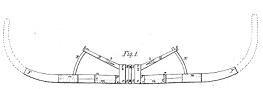
There are two separate moulds or patterns which will shape all the timbers of a boat or vessel. Figures 1 & 2 on the annexed drawings present a side view of one mould. Figures 3, 4 & 5 present a like view of the other mould, the parts coloured red are of wood being of board or plank the parts in blue are of iron.
The red parts A A on figure 1, are in the place of the keel of the boat or vessel and may be of any width or dimensions required. A head of iron B, B, passes around the centre of the mould to give strength and firmness. The blue parts C, C, are movable iron bands which pass around the keel part of the mould and move either way as the keel is to be made wider or narrower. Figure 4 presents a section of these bands, at a is a thumb screw to fasten the bands C, C, when at the right place. — The parts D are arms or shafts made fast to the upper half of the centre part or keel part of the mould, and are set elevated to such an angle as will enable the lower movable parts E, E, when raised to give as much curve or dead rise as is wanted to any timber.
A part of this arm or shaft is of wood. Its junction with the centre piece maybe seen at O on fig 2, which part is there represented as iron and without the iron band, the extreme part of the arm is iron and is joined to the wooden part by a tongue at b. This iron part is offset nearly its whole length as may be seen by its upper surface as in figure 7, so that a curved ganging stake E can move backwards and forwards on the shaft and between the two lips, all the end of this arm at
Page 3.
at C, a thumb screw passing through, so that when lowered the curved rod or slide can move either way as wanted and when made tight the lips of the arm are compressed and hold fast in its place this screw and E. The mould F,F, is fastened by a rivet or hinge to the lower corner of the iron band C,C, at C, it will of course move either way as the band C,C, moves, it is movable on this rivet or hinge and can be dropt to a floor level as in figure 1, or be raised up towards the arm D, as in a part of figure 2, as the timber of the boat or vessel may require to be moulded, This lower part of the mould F,F, on figure 1 & 2 is composed of two pieces of board or plank, below and above so as to slide past each other as may be seen at d,d, on figure 2, a sheet iron band passing nearly around each piece as m,m, on figure 1, and each band forms a socket into which the narrow end of the other piece enters and slides. The mould may be contracted until the band m,m, touch each other, again the mould may be extended until the ends d,d as on figure 2, are drawn almost out of their sockets. An iron plate represented by figure b, is fastened on the upper edge of this bottom part of the mould, this iron plate has an opening or mortise or slit as long as the distance the part d,d, move or slide a screw n on the upper edge of the floor mould F,F, passing through the slit or opening, on the edge plate and enters a firm nut at o. At whatever distance the ends d,d, are drawn from their sockets the screw n may be turned and holds them fast there. The curved gauging rod E is made fast to the floor mould so as to be immovable at that joint. The other ends of E passing through the slit or opening in the arm D, and is there held fast, at any desired position by means of the screw at C. Thus it will be seen that the horizontal motion of the outer part of the floor mould enables one to make timbers of any desired length and the perpendicular circular motion of the whole base F,F, on one side the heel around the hinge axis at C, enables one to erect these timbers from the heel at any desired pitch or angle or at any desired rise.
Page 4.
8|9|1831 6693X
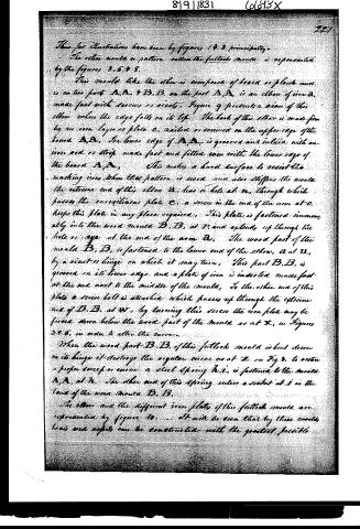
These for illustrations have been by figures 1 & 2 principally.
The other mould or pattern called the fellock mould is represented by the figures 3, 5, 9 & 8.
This mould like the other is composed of board or plank and is in two parts A.A. & B.B. on the part A.A. is an elbow of iron D, made fast with screws or rivets. Figure 9 presents a view of this elbow when the edge falls on its top. The back of this elbow is made firm by an iron layer or plate C, nailed or screwed on the upper edge of the board A.A. The lower edge of A.A. is grooved and inlaid with an iron rod or strip made fast and fitted even with the lower edge of the board A.A. This makes a hard surface to resist the marking iron. When this pattern is used and also stiffens the mould the extreme end of this elbow D has a hole at m, through which passes the enveloping plate C, a screw in the end of the arm at O keeps this plate in any place required. This plate is fastened immovably into the wood mould B.B. at P, and extends up through the hole or eye at the end of the arm D. The wood part of the mould B.B. is fastened to the lower end of the elbow D at U, by a screw or hinge on which it may turn. This part B.B. is grooved on its lower edge and a plate of iron is inserted made fast at the end next to the middle of the mould. To the other end of this plate a screw bolt is attached which passes up through the extreme end of B.B. at W, by turning this screw the iron plate may be forced down below the wood part of the mould as at X, in Figures 3 & 5, in order to alter the curve.
When the wood part B.B. of this fellock mould is bent down in its hinge it destroys the regular curve as at Z on Fig. 3. To restore a proper sweep or curve a steel spring h.i. is fastened to the mould A.A. at h. The other end of this spring enters a socket at i in the land of the wood mould B.B.
The elbow and the different iron plates of this fellock mould are represented by figure 10. It will be seen that by these moulds heads and spits can be constructed with the greatest possible
Page 5.
8/9/1831 6693X
212.
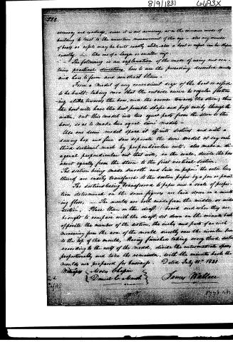
accuracy and expense, since it is not necessary, as in the common mode of building to trust to the uncertain measurement of the eye — also any number of boats or vessels may be built exactly alike, also a boat or vessel can be copied exactly — like one of a larger or smaller size.
The following is an explanation of the mode of using and containing practical directions how to use the preceding described models and how to form and construct them.
Form a model of any convenient size of the boat or vessel to be built, taking care that the outside curve be regular flattening a little towards the bow, and the reverse towards the stern; thus the boat will have the best possible shape and pass easily through the water, cut this model into two equal parts from the stern to the bow, so as to make two equal semi models —
Use one semi model space it off into sections and with a sawing box and fine saw separate the semi model at say each third sectional mark by perpendicular cuts, also make a diagonal perpendicular cut that will, on the wake, divide the bow about equally from the stern to the first vertical section.
The section being made smooth and laid on paper, the outer lines thereof are easily transferred to the section paper by a pen or pencil.
The sections being transferred to paper and a scale of proportion determined on the same figures are laid down on a moulding floor, — The moulds are both made from the middle or wide section, Place them on the draft board and when they are brought to compare with the draft, set down on the minute book opposite the number of the section, the inch and parts of an inch measuring from the arm of the mould directly over the circular bow to the top of the mould, Having finished taking every third section according to the cut of the model, divide the intermediate space proportionally and take the remainder, with the minute book the moulds are prepared for basings. Dated July 9th 1831
Witnesses: Moses Chapin
Daniel C. Smith
James Wallace
1775
Published accounts: journal notice
Notice in the monthly list of patents, with remarks
Journal of the Franklin Institute, new ser., vol. 9 (1832), p. 113 · View the page
15 Timbers for Boats and other vessels; James Wallace, Rochester, Monroe county, New York, August 9.
Remarks. By the invention here patented it is intended to make one set of moulds answer the purpose of laying out timbers for vessels of all sizes. The moulds are to be divided, to have moveable joints and gauges, and to be kirfed in a way particularly explained and laid down in the drawing. The whole arrangement must be shown in order to give a correct idea of the inventor's plan.
DATAMP: illustration
Illustrations from DATAMP

DATAMP (Directory of American Tool and Machinery Patents), via the Internet Archive · Archived DATAMP page
About this record
- Patentee
- the Journal of the Franklin Institute, Journal
- Date
- the Name and Date index of patents, DATAMP, USPTO records
- Invention
- DATAMP
- Listed in
- the Name and Date index of patents, DATAMP, USPTO records, Jim Shaw's X-patent list, the Journal of the Franklin Institute, Burke's List of Patents (1847)
- The patentee's full name comes from the Franklin Institute's journal.
- The residence comes from the Franklin Institute's journal.
- Burke's 1847 Patent Office list gives the same patent.