

Drawings and documents
National Archives restored drawings: drawing
James Stimpson's Patent Drawing for an Improvement in the Mode of Ascending and Descending Rivers and Canals or Inclined Planes

National Archives, Restored Patent Drawings (Record Group 241) · Full-size scan at the National Archives · Catalog record
Show the text on the drawing Hide (343 words)
Words on the drawing as machine-read by the National Archives; not checked. Useful mainly for searching.
p20 / PROPULANCY CA have / CLASS 115,-MARINE PROPULSION. / TOWING, / bity of Battimore State of maryland SS. 19 Internal Power / EASO] Wowing. / James Stimpleon of Battimore, and made Solemn oath, that he interested as inventor in a patent for an im / On day of Inly 1839, before the Rubscriber, a Justice fike peace in and for said city personally appeared / provent in the mode of ascending and descending Rivers & Canals, or inclined planes on Rail Roads be ipued / and dated 20% august 1831, and the drawings underneat with the reference thereto, are, do he / verily #6714 believes, a true deliniation of the Invention ,as described in the said letters patent.- / from to before / CLASSIFICATION / 6714x / Pat aug 23-1831 / DIVISION. / N°1. A side view of a Canal Boat, Canal with the Chain applied to the wheel, for the purpose of propelling it.- / N.,2. A topriew of the shaft and wheels, to lie transversely with the boat, so that by the levers e,e and clutch wheels F.F. for Throwing out of geer, the / wheels on either side of the boat may be used as desired / a,a, Wheels and levers tobe used asbreaks to lessen the velocity of the beat when about to stop.- / No. A side view of a Rail-Road car ascending all inclined plane, by means of The application of chains, which chains should be / applied 012 both sides. / N°4 A topview vzew of apert of 2 RailRoad car, shewing the geers, whereby different speeds may be obtained, to suit slight inclinations / ofthe road, or that the Chains may be used when the grade 2'S sleep.- / №5. A side view of no. 4. The wheels b.b. being unconnecied with the driver C, they can be put into motion by the wheel and / lever d,d,.- / S.S. Dotted lines, the Rail Road wheel.- / Jumes Stempsong / JAMES STIMPSON'S IMPROVEMENT IN THE MODE OF ASCENDING / AND DESCENDING RIVERS & CANALS, OR INCLINED PLANES. / №3 / No1. / №4. / N°2. / e, / e, / P. / of / №5.
USPTO scan
The patent as scanned by the USPTO
-
 Page 1
-
 Page 2
-
 Page 3
-
 Page 4
-
 Page 5
-
 Page 6
-
 Page 7
-
 Page 8
-
 Page 9
-
 Page 10


U.S. Patent and Trademark Office · Google Patents
Show the transcription Hide (4,268 words)
Machine transcription (LightOnOCR) of the pages as scanned by the USPTO, most of them the handwritten copies made when the records were restored after the 1836 fire. Not checked; it can misread handwriting, so compare it with the scan.
Page 1.
SK
OR X 6,714
J. Stimpson,
Towing Vessels
Patented Aug. 23, 1831.
No. 6,714 X

Inventor
James Stimpson
N. A. E. CAL. PHOTO-LITHOGRAPHER, WASHINGTON, D.C.
Page 2.
X0006714
Aug. 23, 1831
James Simpson
Letter Patent
The Schedule referred to in these Letters Patent and making part of the same containing a description in the words of the said James Simpson himself of his improvement in the mode of ascending and descending Rivers and Canals or inclined planes, using such Steam Engines or other locomotive power on board or within the the vessels or vehicles to be moved as may be found necessary for their ascent or descent.
To all whom these Presents shall come
Be it known, that I James Simpson of the City and County of Baltimore and State of Maryland have invented a new and useful improvement in the mode of ascending and descending Rivers and Canals or inclined planes on which locomotive engines or other kind of power, steam, or animal may be used on board or within the vessels or vehicles thereon; and that the following is a full and exact description of the said invention or improvement as invented or improved by me.
Firstly as to the mode of passing over inclined planes, when the nature of the country over which it is intended to build Rail Roads is such that a road must be built on inclined planes, to surmount elevations over which they must pass, and that in so abrupt a manner that the power of locomotive engines, or other powers, or the adhesion of the wheels to the iron plates on which they run would be inadequate to enable them to surmount said elevations, more especially when in combination with snow, frost, ice or water; I propose to use chains of any kind, which may be found most convenient, such as chains used for ships’ cables, or any other that may be preferred, in the following manner; take one or more such chains, stretch them somewhat tight, and make them fast at both ends to something that is firmly fixed in the earth near the foot and top of the incline; and so placed that the said chains may lay their whole length upon the ground, or upon such other supports as may be provided; and on one or both sides of the tracks or in its centre as may be preferred, the links of the said chains should be uniform in length and width, or very near.
Also propose to have for carriages which are used as towing carriages or when passing only by themselves, when they have the power of motion within themselves, a lift or change gear, that the operative power may be changed from the inner
1
Page 3.
2
528.
ate contact with the road wheels of said carriages, to that of a pulley shaft or any other of similar disposition for the same object, which pulley shaft may be placed either at the rear in front of the road wheels, or between them, or anywhere else that may be found the most convenient for it which shaft may have several sets of pulleys side by side upon it, at each end, or if the chains are laid in the centres of the trucks, and sufficient room can be had beneath the bottom of the car, or over, if its case in that place or situation, the pulleys may then be fastened upon said shaft in its middle or centre, which pulleys may be of as many and various sizes as there may be variations of ascent in the different inclines to be passed over, and be all made fast to said shaft side by side of each other, the like number upon each end of said shaft if you have chains, but if you have chains only, and that in the middle, then one set of pulleys will be sufficient; said pulleys should only occupy as much room in the way, as is necessary for their proper strength, and to receive the chains in the centres of their peripheries, having a thin flange between each and on each side of them to serve as a guide to the chains, said pulleys should be made of cast iron or other metal, and be cast in two pieces flat ways, each separated in their centres with the flange upon the side opposite to that which is to join when put together. The form and size of one half of the chain wheel may be seen; must be incident to and accurately cast upon the cage of the peripheries of said pulleys between the flanges so that when two of said pulleys shall be put together upon the shaft, with the flanges out the peripheries of said pulleys between the flanges, will then have earlins or axles of the form and size just right to receive the links of said chains; one link lying flatways in a well sunk nearly or quite its whole depth more or less, below the surface of the peripheries of said pulleys, the next links perpendicularly, the next flat again, and so on alternately throughout their whole surface. I also propose to have a set of small pulleys centred upon one end of a lever that they may be raised or depressed at pleasure by the means of said lever, and to be placed immediately over and to run upon the first named pulleys, but only so thick upon their peripheries as to nearly cover the space between the flanges of those first described; the last mentioned pulleys must have a groove or channel in the centre of them, all round, which channel must be of sufficient width and depth to receive the links of the chains which may lay in the under-pulley's cage ways, or up and around, the surface of the peripheries on each side of said channel should run upon the links which lay flat ways.
Page 4.
3
§29.
lever on which the pulleys must should be centred at a proper distance from said pulleys, upon a fixture also when to the carriage, so that said lever having a handle with a catch or fall attached to it may when the aforesaid chain is to be placed upon the aforesaid under pulley be raised up to allow said chain to pass in between them and then forced down again close upon the chain and to be held by the aforesaid catch or fall. Thus the peripheries of the upper pulley run upon the chain and turn upon their own shaft and pivots by contact merely with the chain holding it down in the culls in the under pulley, to prevent its rising, slipping, or wandering, or the aforesaid under pulley may have with or any other contrivance whereby to hold fast to said chains. These pulleys should be as near to the ground as may be with safety. To use this improvement when you arrive with a car at the foot of an inclined plane, you will stop and place the chains between the pulleys, change the power from the road wheels to that of the pulley shaft; and supposing that the road wheels are three feet diameter, and the inclination of the incline plane about to be ascended is such that the opposition to motion by gravity is just equal to all the friction, or what the opposition to motion would be on the plain or level road, or in other words, if the gravity alone to the friction is such as to require just double the power it did to travel the level road, then put the chain upon a pulley of eight or inches diameter, that being half the size of the road wheels, the same engine or power used upon the plane will enable you to ascend the incline, as there is no loss of power or increase of friction in any degree, the chain being merely raised in front and swept again behind as just in the engine runs upon the road, it is in perfect balance over the pulley with itself all the while, and as there is no wandering movement of the chains upon the ground to be encountered, there can be no loss of power, but the space in this case will be diminished one half during its ascent; when you have arrived at the summit of the incline or a little past, cast off the chain upon the ground, change the power back again to the road wheels, and go on as usual. Again suppose there should be three sets of inclines, all exactly differing one from the other in the angle of their inclination, and that it would be desirable to pass the whole of them with the same engine, then have three sets of pulleys side by side permanently fixed upon the same shaft as before described, each of a size proper for the different inclines to be passed over. Thus the whole length of the road may be travelled with the same power, and that also independent.
Page 5.
independent of the adhesion of the wheel to the rails. Any further degree of power, independent of the size of the pulleys to that of the road wheel may be acquired by placing a large wheel upon the pulley shaft and a small one on the crank shaft which last is to drive the first manner. The necessary change of the power from the road wheel to the pulley shaft or to the locomotive engine, or any other kind of carriages, may be accomplished in various ways; but the following may suffice as one, which will answer, and which should prove. Where roads are arched and much space is desired it will be necessary to use gears, hence two gear shafts and wheels will be already provided for our purpose, another is on the aforesaid pulley shaft and all that will be necessary is to connect the crank shaft that receives the power first from the engine or other power so constructed that it can be made to slide sufficiently to change the contact of the cogs or teeth of the wheel on the crank shaft from the pinion or wheel on the road wheel after to that of the aforesaid pulley shaft whereby the object will be accomplished, and as the necessary movement required is but about two and a half inches, it can be done with safety, by levers or screws, or any other way which may be desired, the box or pillow blocks in which the crank shaft revolves may be connected to long wide iron plates filled close down upon permanent rails or fixtures, which plates we will call slide plates, and we thus as much, and to move them from lateral movement we will have starts or cars projecting from the permanent rail close to the outer edges on both sides and within about six inches of each end of said slide plates, there should be two levers wide enough at the place where centers to cover said slide plates, the handles as splining by each other to a convenient length, said levers to be centered in or upon the aforesaid starts or cars, with a wedge from each from the under side and at the end of said levers, which wedge is to pass down between said plates and a permanent start or fixture to the permanent rails, said wedge to be thick enough to make the necessary movement for the change of the gears, the same at both ends of said plates, there must also be starts within the center of said levers, underneath, extending the whole width and three inches more or less, within its center, the object of which is that when said lever handles is thrust down sufficient to raise the aforesaid wedge to allow said slide plate to move its proper distance, and then immediately after the aforesaid starts underneath the levers is to slide down from said hole fast
Page 6.
that one of said slide plate, the handle end of said lever may be sprung under a spring catch, thereby to hold it securely. It will now be seen, that the handle end of this lever is down and binding said slide plate at that end given up in the rail or its bar underneath and that the average is out, also it should be understood that the opposite lever at the opposite end of the aforesaid slide plate at the average, or its outer end is down and that its average is thrust down between the end of the slide plate and the permanent fixture upon the rail and at the same time the under edge of said lever just within the average, by a small start or projection should come in contact with the upper surface of the aforesaid slide plate, and by a spring catch or prop underneath the handle end of said lever, bind down or hold fast said slide plate as before set forth at the opposite end; thus it will be seen that by casting off the aforesaid spring catches or props, the levers become loose, and also the slide plate beneath them, except one, except which until the levers are moved is or should be held firm by the average, and that by lowering the handle end of the lever that was up, it will raise the average at the opposite end and thereby permit the slide plate to move that way and by raising the handle end of the opposite lever it will thrust down its average and cause said slide plate to move the opposite way, and at the same time confine it permanently on away, and then by passing the handles under the spring catches, &c. it will be confined every way; thus the aforesaid levers are made to move the aforesaid slide plates, whereby a change of gears is effected, and at the same time, serve as binders to hold said slide plates as secure as in any other way. The same application as herein set forth, or aforesaid must be applied at the opposite end of the aforesaid crank shaft. The handle ends of the aforesaid levers which are at each of each other transversely of the carriage, may be connected by a bar which will afford the means of moving the slide plates on each side of the carriage simultaneously; or the aforesaid movement of the crank shaft by that of the aforesaid slide plates may be effected by levers or keys to be set upon as aforesaid by levers, or any other way; the average or key passing the outer ends of the keys in which the journals of the shaft revolve through the cap and bar between which said keys are confined and the pillar blocks or milling there by the slide plates altogether. The chief objection to the aforesaid movement of sliding the crank shaft is that of its connection to the eccentric motion which operates the steam.
Page 7.
6
S. 22.
Means and values which in this case must necessarily be applied in another way, or performed upon some other shaft so placed as to admit of the change, or the variation may be performed by the connecting rods, by its having two centres moving the same way. I also propose another mode, which may be effected as follows; viz. Put two wheels upon the crank shaft: think about the eye and loose upon each shaft, let starts or knobs be cast upon the inside of the rims of such wheels, then fix upon each shaft between such wheels, a slide coupling so made that it cannot turn up on each shaft without turning it, but can move side ways, such coupling may be in form of a blank wheel, with starts or knobs projecting each way, which starts or knobs should be made so as to mesh in between the first mentioned starts upon the inside of the rims of the two gear wheels. Having a groove in each slide coupling in which the end of a lever must be fitted, whereby to move each coupling up to either of such wheels, the starts upon each will interlock each other, by this means this wheel becomes a fixture to each shaft and cannot turn round without each shaft turns with it, the coupling being of itself a fixture to each shaft, in which situation of each coupling it is wholly disengaged from the other wheel. And we will suppose, that this wheel now made fast as aforesaid is in contact with the wheel upon the before mentioned pulley shaft, and thereby puts that shaft into motion, the other wheel upon the crank shaft upon the opposite side of the slide coupling is in contact always with the wheel upon the rear wheel axle, but that being disengaged from the coupling is entirely free to turn loose upon the crank shaft which causes no other friction than simply its revolving upon said crank shaft: the wheel itself performing no operation at that time, all the work being performed by the pulley shaft when the other is loose, change the coupling to interlock the wheel in contact with that on the rear wheel axle and the carriage will be moved by the revolving of the rear wheel and their adhesion to the rail plates, and in this case the pulley shaft will lay still, the wheel on the crank shaft becoming or being of itself loose upon said shaft. The aforesaid change of gears, or the power from one object to the other, may be effected as follows: Place one gear wheel upon the rear wheel axle, one upon the crank shaft, one upon the pulley shaft, all in range of each other, taking care that the wheel upon the crank shaft, does not touch either the one upon the pul
Page 8.
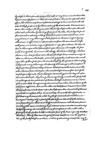
ley shaft, or that upon the road wheel axle at any time, and also that these be permanently fixed in their several places, then centre a fourth wheel upon the short end of lever, so placed as always to be in contact with the crank shaft gear, and by the mechanism of the lever made to come in contact ultimately with the gear upon the pulley shaft or that upon the road wheel axle, and thus by its change from one to the other, the pulley shaft and the road wheel axle may either of them be made to revolve at pleasure, or it may be done in any other way, I also propose in the same way, or by any other means to effect various speeds or powers from the same crank shaft, with gears, in a similar way, only varied in size, for instance, let there be two or three sizes of wheels placed fast upon the road wheels axle, the first with twenty teeth, the second with thirty, the third with forty, also place the same number of wheels upon the crank shaft loose, a reverse in size to those on the road wheels axle, all meshing together at the same time, making either of them fast upon the crank shaft by the aforesaid slide coupling or bayonets or any other way, the speed of the carriage will correspond to the proportions of the variation between the drivers and the driven, and thus when the smallest wheel upon the crank shaft is made fast to it by the couplings or bayonets, that wheel of course meshing into the largest upon the road wheel axle, they having the one say twenty, and the other forty teeth, it will require two revolutions of the crank shaft to produce one revolution of the road wheel, hence you may ascend an incline where the adhesion of the wheels are sufficient, but would otherwise lack power to move a load that the same power would draw upon perhaps an incline twentyths of the route on which we suppose there are no inclines, hence with this application a full load may be moved the whole length of a road which would be an immense gain costing only a part of the speed from twentyths of the distance, and permitting one third or one half more to be drawn with the same power over the entire route, and during high adverse winds a constant motion may be kept by using the variable powers or speeds aforesaid when without them you might be compelled to stop or abandon part of the load or greatly overstrain the boiler. Thus by these variable gears powers, and speeds, and the application of the pulley shaft and chains, inclines of almost any description may be
Page 9.
8
5311.
I propose one with boattails that would be suitable for the engines upon the level road, which, finally, would accomplish with the least possible expense all that has been done by locomotives and stationary power, at a cost of part of the power when passing inclines, which comparing time with power is a gain; for in the proposed plan, the locomotive power will be working constantly with its whole power in any, or all situations, whereas the stationary power would more surely be idle more or less of the time, although kept ever ready for use at great expense, and when used being so connected with ropes or chains, which it has to draw over a long distance, thereby requiring a great power, notwithstanding such ropes or chains may be supported by friction rollers. The whole length of the inclines is an expensive arrangement which by the improvement here proposed will or may be dispensed with.
Secondly, I also propose to apply the same improvement to the boats of the boats, with chains and pulleys as aforesaid, for the use of towing boats or vessels of any kind, in rivers and canals or elsewhere by the means of machinery or one by steam or any other power, applied to the aforesaid pulleys, and they acting upon the chains as aforesaid, said chains should be made fast to each end to such fixtures, and in such suitable places on the rivers, canals, bays, harbours, and elsewhere, as shall be deemed most convenient or useful, and to lay upon the bottom of said rivers, canals, bays, harbours, or under the water, or on any kind of support which may be preferred, there may be two chains one to draw by in one direction, and the other chain for the opposite direction, or one only may be used, with a general understanding that those passing in one direction, when meeting a vessel, shall let go the chain and take it up again, said chains may be made fast by hooks or other ways, to iron bolts in the abutments of locks or such other fixtures as shall be preferred, and in as many different lengths or places as shall be found necessary. In this case the power must be on board of the towing vessel and it should be applied direct to the aforesaid pulley shaft, no change of speed or power being required as in planes and inclines, or it may be in any other way. This application of power in tow boats or vessels acting upon the chains as aforesaid, will do away the necessity of the tow posts, thereby saving the banks of said canals, rivers, etc., and allowing them to be more convenient roads and other purposes.
Page 10.
9
119
535.
10. The aforesaid pulley shaft may lay attached to the wheel with pulley upon which as before described, and of such size, as shall produce a speed comparable with that of the animal, steam, or other power, as may be thought most useful, if animal power be used, it may be upon horizontal wheels, or movable floors such as I use for my patent horse low carriage upon rail roads, or in any other way useful.
What I claim as my invention or improvement is the application of chains to ascend and descend upon rivers and canals, or inclined planes, or rail roads, or otherwise, said chains being made fast at both ends near the foot and top of the incline, and resting upon the ground or other material or at suitable places in rivers or canals, the locomotive or other Engines, drawing themselves up or letting themselves down said incline rivers or canals, by the power which is on board of themselves, by the agency of pulleys in contact with said chains as set forth in this specification, or in any other way, also the variable speeds, or powers herein set forth, or in any other way. For locomotives or otherwise moving carriages upon rail roads, not using the chains. I also claim the application of machinery to change the moving power from the road wheels of locomotives upon rail roads where the inclination is too much for the adhesion of the wheels to the rail plates to allow them to ascend or descend, without slipping or sliding upon said rails, to a pulley shaft as aforesaid, or any other thing, whereby said power is used in a different manner than an immediate contact with the road wheels or their axles as set forth in this specification or in any other way.
Witnesses
William A. Stimpson
Geo. L. Eichelsberger
James Stimpson
4245 words
(Aug. 23, 1831)
Published accounts: journal notice
Notice in the monthly list of patents, with remarks
Journal of the Franklin Institute, new ser., vol. 9 (1832), p. 123 · View the page
36. For an improvement in the mode of Ascending and Descending Rivers, and Canals, or Inclined Planes, using such steam engines, or other locomotive power on board, or within the vessel, or vehicles to be moved, as may be found necessary for their ascent or descent; James Stimpson, city of Baltimore, Maryland, August 23.
Remarks. Firm fixtures are to be made at the upper and lower ends of the planes which are to be ascended or descended, and chains, which may be of the kind used for cables, are to extend from one to the other of them, being supported on the ground, or on fixtures placed for that purpose. A shaft is to extend across the ways of the inclined plane, and when there is a chain on each side of the ways, there are to be cast iron pulleys on each end of the shaft; which pulleys are to be so cast that the links of the chain may fit precisely into them, there being hollows in the middle of them, and indentations in their cheeks, or flanches, for that purpose, which will prevent the chain, as it lies upon them, from slipping. There may be three, or more pulleys, of different sizes, to be used in different ascents. By means of cog wheels, with which the vessel, or carriage, is to be provided, power is to be derived from the steam engine, or animals, &c. within the vessel, to act upon the shaft carrying the pulleys, and thus to make the desired ascent. The specification, which goes much into detail, includes a great variety of propositions, but the following are the claims made. "The application of chains to ascend and descend upon rivers and canals, or inclined planes on rail-road, or otherwise, said chains being made fast at both ends near the foot and top of the inclines, and resting upon the ground or other material, or at suitable places in rivers or canals, the locomotive, or other engines, drawing themselves up, or letting themselves down said inclines, rivers, or canals, by the power which is on board of themselves by the agency of pulleys in contact with said chains, as set forth in this specification, or in any other way; also the variable speeds or powers as herein set forth, or in any other way. For locomotive carriages on rail roads, not using the chain, I also claim the application of machinery to change the moving power from the road wheels of locomotives upon rail-roads where the inclination is too much for the adhesion of the wheels to the rail plates to allow them to ascend or descend without slipping or sliding upon said rails, to a pulley shaft as aforesaid, or any other thing whereby said purpose is used in a different manner than in immediate contact with the road wheels, or their axles, as set forth in this specification." We might here repeat a portion of the remarks made on the last specification, as we think the present claim much too broad. The plan itself, however, appears to us to be altogether impracticable in the form presented, and its details exhibit a want of knowledge in the most advantageous modes of applying power.
Published accounts: journal notice
Notice in the monthly list of patents
Journal of the Franklin Institute, new ser., vol. 17 (1836), p. 269 · View the page
The recipe given is very imperfect, mentioning only one of the ingredients of ink, and is as follows. "A watery extract is made from nut galls, &c. or any other matter suited for making black or coloured inks; thus forming a common writing ink. The whole is then filtered and carefully evaporated, by steam or other heat." Qu. May a person add water to dried up ink? 62. For Turning Short Curves on Rail Roads; James Stimpson, Civil Engineer, Baltimore, Maryland. First patented August 23d, 1831.
Published accounts: journal notice
Notice in the monthly list of patents
Journal of the Franklin Institute, new ser., vol. 17 (1836), p. 277 · View the page
Remarks by the Editor. When wheels, levers, or pistons are in question, we feel as though we could talk familiarly and intelligibly about them; but when "Divitial inventions" and "Accumulative Checks" are upon the tapis, we are among foreigners and strangers whose language we do not underVOL. XVII.-No. 4.-APRIL, 1836. 27 stand. We have never had occasion to become learned in monetary matters, being entirely destitute of the organ of pecuniary acquisitiveness. Under these circumstances we must not be looked to for any explanation of the plan before us, but as some of our readers are versed in the business of stocks and loans, it is, therefore, presented to them for their consideration. Whether the foregoing is sustainable under a patent, does not depend upon its novelty merely, but more essentially upon the determination of the question whether the Art of Finance, can be classed among what are technically called "the useful arts." Specification of a Patent for an improvement in the Mode of Turning Short Curves upon Rail-roads, with Rail-road Carriages, particularly those round the corners of streets, wharves, &c. Granted to JAMES STIMPSON, Civil Engineer, Baltimore, Maryland, August 23d, 1831.
About this record
- Patentee
- DATAMP
- Date
- the Name and Date index of patents, DATAMP, USPTO records
- Invention
- DATAMP
- Listed in
- the Name and Date index of patents, DATAMP, USPTO records, Jim Shaw's X-patent list, the Journal of the Franklin Institute, Burke's List of Patents (1847)
- Burke's 1847 Patent Office list gives the same patent.