

Drawings and documents
National Archives restored drawings: drawing
James Stimpson's Patent Drawing for an Improvement in the Mode of Opening and Shutting Switches on Railroads

National Archives, Restored Patent Drawings (Record Group 241) · Full-size scan at the National Archives · Catalog record
Show the text on the drawing Hide (221 words)
Words on the drawing as machine-read by the National Archives; not checked. Useful mainly for searching.
$2 / bity of Baltimore State of Maryland SS's / Onthis day of Inly 1837, before the subscriber, a Justice of the obth pegce that en he and for said bity personally / James stempson in the mode of Ballimore, of opening and and made shutting solemn Switches a upon Rail Roads, is interested ipued in to him, a patent and / true delineation of the invention as described in the said letters patent.- / dated august 1831; and the above drawings with the references therets, are, as verily believes,a / Issom to Lefore / CLASSIFICATION / James Stempom, / 6716-7 / DIVISION. / Patented Aug. 23d 1831, / Restored Pats vol. 12. p. 519. / 519 / №1. A cross section of the switch as shut and the car about to cross the Track.- / №2. A top view of the switch and car; the switch being opened by means of the connecting rod bac ting upon the / drop a,a, which throws back the lever c,2% MI, 1.- / №3- A side view of the switch d and switch lever e.- / N°4. A Perspec tive view of the switch and switch-box, as seen upon the road._ / 104. RAILWAYS. / 1. The "Way," / JAMES STIMPSONS IMPROVEMENT IN THE MODE OF / 104. RAILWAYS, / [120] Switches. / OPENING & SHUTTING SWITCHES, DON RAIL-ROADS. / Switches, Automatic. / e, / No I. / № 3. / d. / N.,2. / №4
National Archives restored drawings: drawing
James Stimpson's Patent Drawing for an Improved Mode of Turning Short Curves on Railroads, etc.

National Archives, Restored Patent Drawings (Record Group 241) · Full-size scan at the National Archives · Catalog record
Show the text on the drawing Hide (94 words)
Words on the drawing as machine-read by the National Archives; not checked. Useful mainly for searching.
RAILWAYS. Saitahays 4 Fings- / Way," / 20 / Switches. / Spear / lates 26 Lefetember 1835 / fi / JAMES STIMPSONS IMPROVED MODE OF / TURNING SHORT CURVES ON RAIL-ROADS, &c. / TTACK Cams. / Reissued & Patented 26 Sep". 1835. / CLASSIFICATION / 6716'-> / Extended aug 21. for 7 years / DIVISION. / from 23 aug 1845. / A. Aview of the Short Curve / round the cornerof streets. / B. A cross section of the / Gurve at A, showing one / wheel running on its / flanch upon the rail, and / the other on its tread in / the groove. / B. / 60
USPTO scan
The patent as scanned by the USPTO
-
 Page 1
-
 Page 2
-
 Page 3
-
 Page 4
-
 Page 5
-
 Page 6
-
 Page 7
-
 Page 8


U.S. Patent and Trademark Office · Google Patents
Show the transcription Hide (2,520 words)
Machine transcription (LightOnOCR) of the pages as scanned by the USPTO, most of them the handwritten copies made when the records were restored after the 1836 fire. Not checked; it can misread handwriting, so compare it with the scan.
Page 1.
6716X
J. Stimpson.
Railroad Switch.
Patented Aug. 23, 1831.

Witnesses:
[signature]
Inventor:
[signature]
THE GRAPHIC CO. PHOTO-LITH. 39 & 41 PARK PLACE, N.Y.
Page 2.
Aug 23, 1831 6716X 574
James Simpson
255555 565555
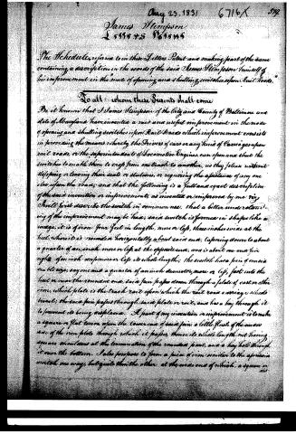
The Schedule referred to in these Letters Patent and making part of the same containing a description in the words of the said James Simpson himself of his improvement in the mode of opening and shutting switches upon Rail Roads.
To all whom these Presents shall come
Be it known that I James Simpson of the City and County of Baltimore and State of Maryland have invented a new and useful improvement in the mode of opening and shutting switches upon Rail Roads which improvement consists in providing the means whereby the Drivers of cars or any kind of Carriages upon rail roads, or the superintendents of locomotive Engines, can open and shut the switches to enable them to cross from one track to another, as they please without stopping or leaving their seats or stations, or requiring the assistance of any one else upon the roads; and that the following is a full and exact description of the said invention or improvements, as invented or improved by me viz.
I will first describe the switch in common use, that a better understanding of the improvement may be had; said switch is formed in shape like a bridge, it is of iron four feet in length, more or less, three inches wide at the heel, where it is rounded horizontally about said end, tapering down to about a quarter of an inch more or less, at the opposite end, and is about one and five eighths of an inch deep more or less, its whole length; the switch has a pin of considerable size, say one and a quarter of an inch diameter, more or less, fast into the heel or near the rounded end, said pin passes down through a plate of cast or other iron, which plate is the track rail upon which the rail road carriage wheels travel; the said pin passes through said plate or rail, and has a key through it to prevent its being misplaced. A part of my invention or improvement is to make a square or flat tenon upon the lower end of said pin, a little flush of the inner side of the iron plate through which it passes, thence its whole length out having square shoulders at the termination of the rounded part, and a key hole through it near the bottom. I also propose to form a piece of iron similar to the aforesaid switch one way, but quite thin the other, at the wide end of which, a square or
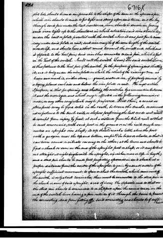
Page 3.
6716X
slot hole, should be made as conformable to the shape of the beam on the aforesaid pin, which iron should be made to fit tight and strong upon said beam, and the key through said pin under the last mentioned iron, should be driven in, forcing said iron tight up to the shoulders, in which situation said iron should lay under the rail or plate parallel with the switch above it and just free to move easy under said plate or rail; said iron may be of the same length of the switch more or less, and should have a short round tenon at the small end, which end is opposite to the heel pin; said iron thus connected to said pin, which is fast in the heel of the switch. I will call the switch Lever; The said switch Lever, is thus fastened to the heel pin of the switch, for the purpose of opening and shutting it, and it being under the iron plate on which the wheels of the carriage run, no harm can reach it, neither stones, gravel, water or ice, if properly secured by a bogy placed each side and below the iron plate or rail. The next article I propose, is, that for opening and shutting the switches, by a connection between it and the carriages, and which may be effected, in the following manner or mode, or any other way which may be preferred. First then; a wood or stone post may be fixed solid in the earth, between the tracks, or connected or fastened to the track rails, or sleepers preferring the last mode as it would be exempt from injury by frost; at such a distance from the track rails as shall be most convenient; with said post in the ground or on the rails may be connected an upright iron shaft; its top should reach a little above the post with a guayon near the top and bottom, confined in boxes or brackets, so that it can turn round or vibrate one way or the other; at the lower end should be fixed a shank or arm on the end of the upright post or shaft, or it may be bent out straight at right angles with the upright, six inches, more or less, in length; and a steel pin should be made fast projecting upwards in said shank at a proper distance from the centre of the upright, to gain by a small motion of the upright sufficient movement, to open or shut the switch, which movement of the switch, is only about two inches; there must be connected to the steel pin in the shank or arm of said upright, a rod of iron; the opposite end to that on the steel pin should be connected to or slotted upon the round tenon on the end of the switch lever having a pin outside of it through the tenon to prevent the connecting rod from getting off; said connecting rod should be of sufficient
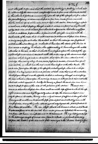
Page 4.
event strength to open and shut the switch by pushing or pulling, which will be alternately the movement necessarily made to open and shut said switch; there should be fastness immovably upon the top of the upright shaft a rhombus, parallelogram, or diamond shaped wire lever made of iron one inch thick, more or less, six inches wide, one or less, in the centre, terminating in a point at each end, a shaft passing through or into it, as near one point as may be with safety; said iron at its widest part should be only so wide that when any single article or substance passes within its point at the upright on a line with the track rails, of the road; that it will cause said diamond shaped iron to move or swing out, so far as to close the switch so that the carriage can pass said switch without entering it: or should it have been the desire of the Driver to have made a crossing, he should when approaching it, have changed the article attached to his car, so that it should have passed upon the outside of the upright shaft and come in contact with the outer edge of the diamond shaped iron, which being so wide in its middle, that before the iron attached to the carriage thus moving along its side, could pass said middle, it would have opened said switch, in which case the car would have crossed to the other tracks. The said iron fixed upon the top of the upright, vibrating shaft, should be in shape similar to a long narrow diamond, pointed at both ends, that is, at the end where the shaft goes through and the opposite, so that in returning through said crossing, the iron which is fixed upon the carriage to move or vibrate said diamond with, shall not clash against it, but by its having a point the said iron can be made to pass it upon either side at the pleasure of the driver. The said diamond or rhombus shaped iron lever, will cover the top of post to which the upright is connected and lay horizontally above its top, the diamond shaped iron may be open in its centre, having a rim only all round of sufficient strength, which opening will enable me to cover the top, of each post and vibrating iron, with a cap of iron, or anything else, extending each way beyond the post to protect it from harm or weather. The iron shaft should also be casted about, and a trunk be extended from it to the switch lever under ground, to protect the connecting rod from all harm, or infestation to its movement. The regulating rod, upon the carriage, made of round iron fixed to vibrate in journals extending up from the bottom of the side rails of the carriages to the Drivers having a hem
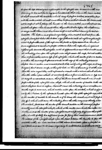
Page 6.
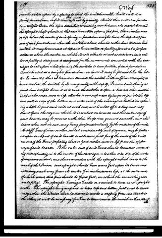
iron be acted upon by a spring to shut the switches with, I will call it a spring pendulum, or if it should be made to act by gravity, I will then call it a pendulum weight lever, the before described connecting rod between the switch lever and the upright shaft should in this case be centred upon a fast pin, three inches, more or less, below the centre of said spring or pendulum weight lever, the top or upper end of said pendulum when the switch is closed, should rather lean towards said switch it may be nommed at top and have a roller or pulley upon it at a proper distance above the centre on which it is to vibrate or not as desired; said roller or pulley is designed for the movements connected with the carriages to act upon while opening the switches to save friction, if said pendulum should be used as a weight pendulum or lever it may be formed like the letter L inverted thus I turned in towards the switch with sufficient weight, to move or close the switch by its own gravity with safety, To move said spring or pendulum weight lever, so as to cause the switches to open, a board or other material six inches wide, more or less, althought to and suspended by hinges or joints to the top and outside edge of the bottom and outer rails of the carriage or both sides extending a little beyond said rails at each end, and beveled off to a long and easy slant from the edge on which it is centred on towards, and this outer edge of said board, may be covered with thin hoop iron ground smooth, and said board when not in use, may hang perpendicularly by the outsides of the rails. A stiff fence of iron or other metal considerably out of square, may be fastened upon each end of said boards, so as to move just free of the ends of the rails. one end of the fence projecting three or four inches, more or less from the upper edge of said boards. To the outer end of said fences should be centred connecting rods extending in to the centre of the carriage, or to either side side of the centre if more convenient, and there connected with the upright which leads to the back of the Driver. said upright should have arms fast upon its lower end extending each way from its centre five inches, more or less, at the outer ends of which arms, two pins should be fixed fast, on which the connecting rods are to play. The upright having a handle or a switch to turn said upright with. The upright being confined in boxes top and bottom just so as to move easy when the Driver should desire to make a crossing from one track to the other, it will be necessary for him to turn round the switch or handle of
Page 7.
the upright sufficiently to raise the boards or tines on each side of the carriage on horizontal line in which position as he pushes the spring or pendulum lever, the outer edges of said boards should come in contact with the roller or pulley upon the top end of said pendulum, and cause the top end of said pendulum lever to move out and thereby open the switch. Said boards extending the whole length of the carriage, the switch will be kept open until after the hind wheels shall have entered said switch, and as soon as the boards shall have passed the pendulum lever, the switch will immediately reclose, in which position it would be most desirable it should continue, as in that position, it would keep out stones, dirt, ice, or snow; and when the switch was forced open all those articles of obstruction if about it would slip into the path before it, and thus leave it free to return again to its former place; if the switch was generally left open all the aforesaid articles might accumulate with in it, and thus would necessarily have to be removed by the attention of some person before the switch could be closed. If the carriages are not turned about at each end of the line, it will be necessary to have the uprights as aforesaid at each end and the same in the first mentioned case or operation. The post to which the pendulum is connected may be casted and capped to enclose all the irons about it except in the range of the top end of the pendulum lever, where the boards or other fixtures attached to the carriages, pass in the range of which, a notch should be cut into the post and casing under the cap, to be of sufficient depth to allow said boards to produce all the necessary movement upon said pendulum, and yet allow the cap above to secure it from any injury from the weather &c. &c. trunk as before described, in all cases leaving from the post under ground to the switch, will protect the connecting rods &c. and thus should not be omitted. The uprights first described connected to the carriage may be only of sufficient length from the crank up to reach just above the top of the carriage rails to which they are fastened. The top end bent out at right angles, may be six inches long, more or less, and serve as a wind or lever to turn it with, with a stay firmly fast in the outer end, on which to continue iron rod, said rod to extend thence into the centre of the carriage, or as near it as may be found convenient. The said connecting rod is to be connected on its inner end to the upright which reaches to the Driver, and in all respects as described in the other case, and if the carriage should not always travel one way first, it will be necessary to have the aforesaid crank irons at the four corners of the carriage.
Published accounts: journal notice
Notice in the monthly list of patents, with remarks
Journal of the Franklin Institute, new ser., vol. 9 (1832), p. 122 · View the page
" What I claim as my invention or improvement, is the application of cast iron for the platform of the turnabout, in form aforesaid, or any other manner. Also the construction of turnabouts as above set forth. Also the double tracks on turnabouts at right angles with each other, as herein set forth. Also the cheek bolts for fastening turnabouts in their proper positions by its own movement, caused either by gravity, or otherwise, for any kind of turnabouts. Also the stone or brick curbing surrounded with iron plates, as above set forth, or otherwise. Also the connecting the track rails with those under them, and the transverse timbers for security against frost, &c., as used as the foundation of turnabouts, as above set forth, or otherwise." We think the above claim rather too comprehensive and sweeping throughout; we doubt the validity of a claim, for example, to the application of cast iron for the platform, in form aforesaid, or in any other manner, &c. &c. 35. For an improvement in the construction of Wheels for Rail-road Carriages; James Stimpson, city of Baltimore, Maryland, August 23.
Remarks. It is observed in the specification that the side of a wheel to which the flanch is attached, is much the strongest, whilst the opposite side is the most subjected to those accidents which tend to break the wheel; the improvement proposed is to strengthen this side of the rim by a ring of additional metal in the casting; and the patentee says he has no doubt that fifteen pounds of metal, forming such a ring will give more additional strength to the wheel, so as more effectually to protect it from breaking, than one hundred pounds equally distributed throughout the whole of the rim. The claim is to "the application of the rim, ring, or felloes, inside of the tread, or rim, or inner periphery of the wheels, opposite to the flanch."
Published accounts: journal notice
Notice in the monthly list of patents, with remarks
Journal of the Franklin Institute, new ser., vol. 9 (1832), p. 124 · View the page
38. For an improved mode of Opening and Shutting Switches on Rail-roads; James Stimpson, city of Baltimore, Maryland, August 23.
Remarks. Those who know any thing of rail-roads are aware that what are called switches, are pieces of iron employed at turn out places, which pieces, or bars of iron, have to be opened and closed, according to the track upon which the carriage is to travel, and that accidents have frequently occurred in consequence of the switches not being opened or closed as required. The plan proposed in the specification of the above patent, is to arrange certain levers, and other machinery, so that a piece projecting from the carriage shall operate upon the switch and give to it its proper direction, either by day or night, without personal attention on the part of the person having the care of the carriage. The claim is to "the application of machinery to open and shut switches, whereby the drivers of carriages, or superintendents of locomotive engines, or others, without stopping, or leaving their seats, carriages, or horses, can open and shut switches, if in order, by night, or by day, without seeing them, by machinery, as set forth in the above specification, or in any other way or manner." The contrivances proposed, " if in order," might answer the purpose, but from their complexity, we apprehend that they would prove to be traps rather than protectors.
About this record
- Patentee
- DATAMP
- Date
- the Name and Date index of patents, DATAMP, USPTO records
- Invention
- DATAMP
- Listed in
- the Name and Date index of patents, DATAMP, USPTO records, Jim Shaw's X-patent list, the Journal of the Franklin Institute, Burke's List of Patents (1847)
- Burke's 1847 Patent Office list gives the same patent.
Shaw: lists Stimpson, J. here as 6516½