

Drawings and documents
National Archives restored drawings: drawing
James Stimpson's Patent Drawing for an Improvement in the Construction of Railroad Wheels

National Archives, Restored Patent Drawings (Record Group 241) · Full-size scan at the National Archives · Catalog record
Show the text on the drawing Hide (54 words)
Transcribed by GraceBrinson for the National Archives.
James S Timpson's improvement in the construction of rail-road wheels. A. A perspective view of the rim of the wheel, shewing the internal flanch a_ B. A cross section of the wheel, shewing the internal flanch b; diagonally opposite to the external one.c. Patented Aug. 23. 1832
USPTO scan
The patent as scanned by the USPTO
-
 Page 1
-
 Page 2
-
 Page 3
-
 Page 4
-
 Page 5
-
 Page 6


U.S. Patent and Trademark Office · Google Patents
Show the transcription Hide (2,035 words)
Machine transcription (LightOnOCR) of the pages as scanned by the USPTO, most of them the handwritten copies made when the records were restored after the 1836 fire. Not checked; it can misread handwriting, so compare it with the scan.
Page 1.
6719X
J. STIMPSON.
Car Wheel.
Patented Aug. 23, 1831.

AM. PHOTO-LITHO. CO. N.Y. (OSBORNE'S PROCESS.)
Page 2.
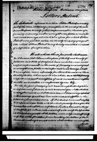
Aug 23 1831. Signed Sept 26 1831 6719x 227
Entered for the clerk of the court 23rd August 1831
James Simpson 1831. Baltimore, Maryland.
Letters Patents.
The schedule referred to in these Letters Patents and making part of the same, containing a description in the words of the said James Simpson, himself of his improvement in the mode of forming and using, cast or wrought iron plates or rails for rail road carriage wheels to run upon, for which Letters Patent were granted dated, the twenty third day of August 1831, which Letters Patent being hereby cancelled on account of a defective specification.
To all whom these presents shall come.
Be it known that I James Simpson of the city and county of Baltimore and State of Maryland, have invented — now and useful improvements in the mode of forming and using cast or wrought iron plates or rails for rail road carriage wheels to run upon; more especially for those to be used on the wheels of flat cars, wharves and elsewhere; and that the following is a full and exact description of said invention or improvements, as invented or improved by me.
For the purpose of carrying rail roads through the streets of cities and of traversing the same in rail road carriages, whether the streets be straight or curved and at the same time not to cause any impediment to other carriage operations, I use rails made and applied in the following form and manner. If it is desired to use cast iron plates laid upon wrought iron rails, and the wheels generally to run upon this heads, I so construct them as follows. I make a channel in the top of the plate not out one inch and a half wide across the top and about two and a quarter at the bottom, more or less, and sufficiently deep to prevent the flat wheels from touching the bottom of the channel, making a small curve at the bottom corners of the channel.
Page 3.
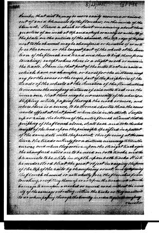
buckles, that will be, may be more easily removed or raised out of said channels by the flanches; on the inside of the channel, I leave a cheek or bar measuring about three quarters of an inch at top and as high or nearly so at the top of the plate on the outside of the channel, the top edge of the plate next to the channel may be chamfered or bevelled if so not to free the cones, or the largest part of the wheels at the junction of the flanch and tread and thus to keep them from touching; except where there is a slight work or curve in the tracks. I then in that part of the outer track use rails in which have no chamfer, or bevel for the distance necessary for the cones or the larger part of the peripheries of the heads of the wheels at the junction of the flanch then to measure the necessary distance of said outer track over the inner one, that there may be no necessity of the wheels slipping while passing through the work or curve, and where there is a curve, to be turned shorter than the cones would effect at that point, when laid in the tracks. I so pile up or raise the bottom of the outer flanch channel that the periphery of the flanch alone, shall bear, and take the whole weight of the load upon the principle specified in a patent of the same date with the present, thus freeing at the same time the treads entirely for a distance necessary to turn the curves, and when they arrive upon the straight track again the chamfered rails are to be used on both tracks, and the channels to be alike in depth upon both tracks. It is to be understood that the great object in varying the form of the top of the rails by chamfering or not, and by giving the flanch channel so as to wholly free the flanches from touching, or so filling them up as to free the treads, is to allow the carriage to run upon a crooked or curved road without the necessity of the carriages vibrating within the tracks as they are allowed to do when passing through the curves in order to gain the necessary elevation.
Page 4.
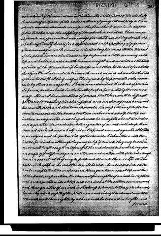
variation of the elevation in the diameter in the tracks of the wheels, by throwing away surfaces of the rails instead of giving lateral play to these wheels, narrow channels were for the flanges to run in, in all parts of the tracks, and the slipping of the wheels is avoided. These narrow channels are of essential advantage for their use as they obviate the whole difficulty hitherto experienced in the piling of girders and other carriages with narrow wheels along the same tracks; The part of the plate under the tracks may be formed a little narrowing on the top and hollow underneath to save weight and as wide as the track outside of the flanges if laid upon wooden rails as before stated, the object in this would be to cover the work as wide at least as the tracks of the wheels, that they may not be injured by the pavement, or the wooden rails by other carriages. I have now described this kind of plate in its form, and as laid in the tracks proper for a straight or curved way. It must be understood of course that there must be different patterns for casting the chamfered and unchamfered rails and those with deep and shallow channels. The projection of the plate, should measure on the base about six inches and a half, the top six inches and a quarter, and they should be in depth about two inches and a quarter, the inside about three quarters of an inch in thickness, the channel one inch and a half wide at top, and one and a quarter at bottom or nearly so and the part outside of the channel which will be under the tracks, four inches although they may be less if desired, they may be cast in convenient lengths say three to four feet, the end should be bevelled, say upon an angle of forty-five degrees, or a tenon and mortice with spike holes through them in order that they may be fastened down to the wood or stone rails with spikes. In most cases, I should when bedded into stone rails use plates two inches and three quarters wide at top and three at the base, projection, the channel five eighths of an inch in depth from inch and a quarter wide at top and one inch at the bottom, or narrow way, and three quarters of an inch in thickness below the bottom of the channel, hence the whole depth of the plates on each side of the channel would be one inch and three eighths by a three inch base; and in length one and a half formed.
Page 5.
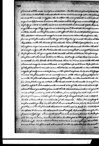
formed at the ends, as before mentioned. In this kind of rail, the intention is that the wheels shall run, and bear only upon their flanges, and this mode is by far the best for the use of streets in cities, for it requires less power to move the cars while they are undoubtedly as safely guided, and the rails are as durable and much lighter than in any other way, they require no clearing out, to which the deep ones will be liable, as the flanches will effect this in such shallow grooves. The shallow channels may be made narrower than the deep ones, the form of the flanches admitting this, they being much thicker at their juncture with the treads of the wheels than at their peripheries, and therefore require more room in the deep channels to allow the dist to rise freely out. But should the common flat wrought iron rails be preferred, they may be laid double all the distance, thus forming the flanch channel between them, but only where there is a curve or crook in the tracks to be turned, then in those curves the outer channel may be discontinued, or as filled up as to have the peripheries of the flanches bear alone on that side or the plate on the outer track may be of only one wide piece, with a flat surface laid contiguously under the flanches and nearly even with the surface of the pavement, the flanch channel being left entire, on the inside track; or an iron plate may be rolled with the channel in the centre in one piece, that is a plate two inches wide on each side of the channel, more or less, about three quarters of an inch thick, channel one inch and a quarter wide at top and one inch at bottom, five eighths of an inch deep, all the plates of the same thickness throughout if wrought heat, and with like holes alternately on each side of the channel. Where it is necessary to cast a water gutter in the street, there a cast iron plate to cover said gutters, with the flanch channels cast inside plate and all the space between the channels cast rough, to prevent horses' feet from slipping. It may be cast in one or more pieces but is preferred being in one, as it will then be stronger although of the same thickness, and where there are curves and crooks a gutter at the same time the flanch channel will in that case be cast
Page 6.
conformably to the curve and only on the inner track of the circle, while the outer track may be left flat and smooth without humps just even with the top of the coping or a triple below it if desired upon the principle explained in the said patent before alluded to. The former cast iron plate which covers the water gutters, being cast in one piece and of a width sufficient to cover any street gutter, should have ribs cast underneath about one inch and a quarter deep below if the thickness of the plate, just under the outer edge to increase its strength. In some cases I cover the gutters the whole width of the street with cast iron plates and some distance past the curbings thus making a very great improvement to the street for the ordinary travel. It will be observed that the nail plates are directed to be made widest upon their bases, the effect of which is that when sunk into a channel in the centre of a stone or wooden rail the pressure of wood into the seams on each side of the iron by the common carriage wheels rolling over them will confine the iron plates between the joints of the stone or wood. What I claim as my inventions or improvements are the employment of plates or nails either of cast or wrought iron constructed upon the principle or in the manner herein described, having narrow grooves for the flanches to run in by which they are perfectly adapted to the most varied paving of all kinds of pavings used in streets over them. The rounding of the peripheries of the flanches or of the cone, or rise on the head of the wheel upon the rail in the manner set forth for the purposes set forth, and the employment of plates upon cast iron upon the principle described for the coping of gutters, and the ironing of curbs. And I do hereby declare that I do not intend to confine myself to the precise forms and dimensions given, there being intended merely to exemplify in a clear manner the nature, object, and mode of carrying into effect my said inventions.
Witnesses
James W. Thompson
Geo. B. Banniman
James W. Thompson
Ex.
app.
About this record
- Patentee
- DATAMP
- Date
- the Name and Date index of patents, DATAMP, USPTO records
- Invention
- DATAMP
- Listed in
- the Name and Date index of patents, DATAMP, USPTO records, Jim Shaw's X-patent list, Burke's List of Patents (1847)
- Burke's 1847 Patent Office list gives the same patent.