

Drawings and documents
National Archives restored drawings: drawing
Thomas Ewbank's Patent Drawing for a Hydrostatic Safety Valve

National Archives, Restored Patent Drawings (Record Group 241) · Full-size scan at the National Archives · Catalog record
Show the text on the drawing Hide (56 words)
Words on the drawing as machine-read by the National Archives; not checked. Useful mainly for searching.
DC 136. VALVES Values / THOMAS EWBANK'S / [148] Safety. / Steam Engines / Hydrostatic Safety Valve. / Patented August 27. 1851. / $1- / Fig. 1. / Fig 2 / CLASSIFICATION / vol12 page 111 / 6736.4 + / D X / E F / FL / DIV ISION. / E/5 / 11th / Fig4 / Fig. 3. / Fig5. / 35. / PP / 50 / to / 40. / DY / 30 / EX / 20 / FX / 70 X H / 5C
USPTO scan
The patent as scanned by the USPTO
-
 Page 1
-
 Page 2
-
 Page 3


U.S. Patent and Trademark Office · Google Patents
Show the transcription Hide (813 words)
Machine transcription (LightOnOCR) of the pages as scanned by the USPTO, most of them the handwritten copies made when the records were restored after the 1836 fire. Not checked; it can misread handwriting, so compare it with the scan.
Page 1.
6736X
T. Ewbank,
Steam Safety Valve.
Patented Aug 27, 1831.
Fig. 1.
Fig. 2.
Fig. 4.
Fig. 3.
Fig. 5.
AM. PHOTO-LITHO. CO. N.Y. (OSBORNE'S PROCESS)
Page 2.
Thomas Tipton
The Schedule, upon which is this Letter Patent, and making part of the same, containing a description, in the words of the said Thomas Tipton himself, of his improvement in the safety valve for Steam Engine Boilers, denominated the Hydrostatic Safety Valve.
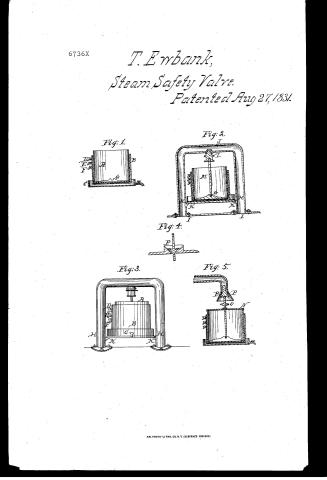
To all whom it may concern: Be it known that I Thomas Tipton, of the city of New York, have invented a new safety valve for the boilers of Steam Engines, which I denominated the Hydrostatic Safety Valve, and that the following is a full and exact description thereof. The form of my safety valve may be the same as that ordinarily used, namely a truncated cone; instead however of being pressed downwards in the usual way, it is forced upwards by the weight of a column of water, mercury or other fluid. In the accompanying drawings, those parts which are similar in the different figures, are represented by the same letters. Figure 1 represents a section of the vessel by means of which the hydrostatic pressure is made. A is a cylindrical vessel which may be open at top but is closed at bottom. This is placed within a second vessel B, which is to contain water or other fluid, by which the pressure is to be made. It is evident that when the vessel A is placed within the vessel B and water is forced into the cavity between them, A will be forced upwards, with a force proportional to the area of the bottom of A, and the altitude of the fluid in the cavity. C is a shallow well in which B stands and is intended to receive any fluid which may escape from B. D, E, F are cocks placed in B to regulate the height of the fluid, and consequently to graduate the pressure, say to 50, 60, 70, and so on to the square inch. G is a disk of iron or other light material, intended to stiffen the bottom of A, and which may also serve to receive the lower end of the valve rod, each end of which passes into cavities without the use of joints, as ordinarily made. Fig. 2 is a section of the valve in action. H, H is a tube one or both ends of which, open into the boiler at D. The inverted valve seat is seen at S in the upper part of this tube. K, K are latches to support the hydrostatic apparatus above the boiler, a piece of plank or other the conductor is usually first placed upon the latches. The valve rod is neither clamped in its lower side to receive the iron H, the lower end of which rests on G. Fig. 3 is a perspective view of the whole apparatus, the graduation by means of the cocks being represented by figures. As the steam is blowing off
Page 3.
8/27/1831 67316X
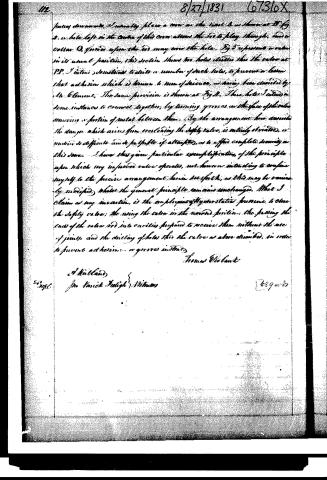
James downward, I usually place a cover on the vessel A in figure at B Fig 2. a hole left in the center of this cover allows the air to play through, and a cotton Q, formed upon the rod may cover the hole. Fig 3 represents a cover in its usual position, this section shows two holes similar to the valve at PP. I intend sometimes to drill a number of such holes, to prevent a layer that adheres which is known to men of science, as having been described by Mr. Clement. The same provision is shown at Fig 4. These holes I intend in some instances to connect together, by turning grooves in the face of the valve removing a portion of metal between them. By the arrangement here described the danger which arises from encroaching the safety valve, is entirely obviated, or rendered so difficult and so futile of attempts, as to afford complete security in this sense. I have thus given particular exemplification, of the principle upon which my improved valve operates, not however intending to confine myself to the precise arrangement herein set forth, as this may be variously modified, whilst the general principle remains unchanged. What I claim as my invention, is the employment of the statical pressure to close the safety valve; the using the valve in the second position; the passing the ends of the valve rod into cavities prepared to receive them without the use of joints; and the drilling of holes into the valve as above described, in order to prevent adhesion or grooves instead.
Thomas W. Clark
A. R. Holland
Pro. Varick Peleigh & Williams
689 w 83
Published accounts: journal notice
Notice in the monthly list of patents
Journal of the Franklin Institute, new ser., vol. 9 (1832), p. 133 · View the page
58. For a Hydrostatic Safety Valve for the boilers of steam engines; Thomas Ewbank, city of New York, August 27.
About this record
- Patentee
- DATAMP
- Date
- the Name and Date index of patents, DATAMP, USPTO records
- Invention
- DATAMP
- Listed in
- the Name and Date index of patents, DATAMP, USPTO records, Jim Shaw's X-patent list, the Journal of the Franklin Institute, Burke's List of Patents (1847)
- Burke's 1847 Patent Office list gives the same patent.