

Drawings and documents
National Archives restored drawings: drawing
Daniel Treadwell's Patent Drawing for a Machine for Spinning Hemp, Flax, and Other Fibrous Material


National Archives, Restored Patent Drawings (Record Group 241) · Full-size scan at the National Archives · Catalog record
Show the text on the drawing Hide (176 words)
Words on the drawing as machine-read by the National Archives; not checked. Useful mainly for searching.
Sheet 1. Daniel headwell / 10 / 917- / Spinning hemp,flax & Bo:1 other fibrous material Patented 10 "Ocl: 1831. / ITATIO / #6794X / If / bf / OF / If / If / of / 3f / be / BY / 20 / Hg / ya / bg / 79 / 3h / 3h / be / The / qa / 2g / be / 1k / 6e / Ba / 5b / If / be / Se / 40 / THE / Scale f Thet
Sheet 2. NOISIAN ICI / X XhbL9# / 09 / (S) / Фр. / A. / to / PL / gd / of / "I / of / 19 / be / 6794) 67 / be / 9c / C/2 / all / 20 / The / PC / be / fL / of / If / fg / be
Sheet 3. ISION / 6794 X / So / H. / The: e / DI / PE / 5c / be / b. / 4e / FigH / of / Eg:6 / Sa / Flo. 8 / Fig:" 7 / 6:8m / ohr / OHA / SE / 5a / II / 4a / Fig. 12 / Fw:10 / 5a / 5d / F10:13 / EA / 5d / S.c / 8d / 7d / 3a / 76 / 6b / 7a / 4d / Ta / Fig:4 / yo / 6d / Da
Sheet 4. CLASSI FICATION / #6794 X / DIV ISION / be / If / 2h / 2½ / 7g / bg / 6h / bg / Ih / ge / Se / be / FID. 16 / Ih / 2g / 4g / 5g / bg / 7k / yl / Ah / 8h / ye / 5h / be / If / if / 1h / 9g / 6h / In / of / is / be
USPTO scan
The patent as scanned by the USPTO
-
 Page 1
-
 Page 2
-
 Page 3
-
 Page 4
-
 Page 5
-
 Page 6
-
 Page 7
-
 Page 8
-
 Page 9
-
 Page 10
-
 Page 11
-
 Page 12
-
 Page 13
-
 Page 14
-
 Page 15
-
 Page 16
-
 Page 17
-
 Page 18
-
 Page 19
-
 Page 20
-
 Page 21


U.S. Patent and Trademark Office · Google Patents
Show the transcription Hide (9,791 words)
Machine transcription (LightOnOCR) of the pages as scanned by the USPTO, most of them the handwritten copies made when the records were restored after the 1836 fire. Not checked; it can misread handwriting, so compare it with the scan.
Page 1.
6794X
D. Tredwell.
Spinning Fibrous Material.
Patented Oct. 11, 1831.
Sheet 1 - 2 Sheets.
Fig. 1.
Fig. 2.
Fig. 3.
Fig. 4.
Fig. 5.
Fig. 6.
Fig. 7.
Fig. 8.
Fig. 9.
Fig. 10.
Fig. 11.
Fig. 12.
Fig. 13.
Fig. 14.
Fig. 15.
Fig. 16.
Page 2.
No Printed Specification Available
6794X
D. Treadwell. Sheets 2-2 Sheets
Spinning Fibrous Material.
Patented Oct. 11, 1831.
Fig. 4.
Fig. 7
Fig. 8
Fig. 9
Fig. 10
Fig. 11
Fig. 12
Fig. 13
Fig. 5.
Page 3.
6794X
Daniel Treadwell of Boston Mass.
Letters Patent dated Oct 11, 1831.
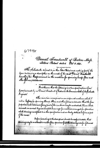
The Schedule, referred to in the Letters Patent and making part of the same containing a description in the words of the said Daniel Treadwell himself of his Improvement in the machine for spinning hemp, flax and other fibrous substances.
Be it known that the following is a true specification of an Invention made by me Daniel Treadwell of Boston in the Commonwealth of Massachusetts Engineer.
This invention is comprised in an improved machine, which I call a Lyspey for spinning Hemp, Flax, and other fibrous substances. That the form, proportions and relations of every part of the machine may be understood, I have hereto annexed, in several figures, complete drawings of a machine arranged for operation which drawings are referred to in this specification and are hereby declared to form a part of the same.
Before proceeding to the description, it will be useful to state that spinning may be considered to consist of two operations, first the drawing out of a filament
Page 4.
292 6794X Oct 11, 1831
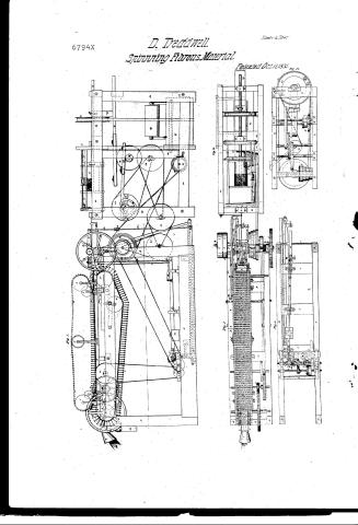
of the required fineness from a mass of the fibrous material commonly in the state of a roving or roll and second, the twisting of the filament so drawn, which completes the formation of the thread or yarn. In some modes of spinning both of these operations are carried on at the same time in the same portion of the material that is the filament is elongated during the operation of twisting. In the invention herein described the filament is drawn to the proper size before twisting it in any degree: and it will be hereafter seen that this improved machine or gypsy, consists of two distinct parts viz: the part represented in figures 1, 2, 3, 4 and 5 by which a small filament is drawn from a column or roving; thus for the sake of distinction I call the drawing frame and the part represented in figures 15 and 16—this I call the bobbin frame. The drawings herein referred to, were reduced from and represent a machine for spinning rove yarns.
The size of the several parts of the drawings, is to that of the machine as 1/4 inches is to a foot. The scale under figure 1 is applicable to all the figures. Machines for fine threads or linen yarns are necessarily made smaller than that here given in proportion to the fineness of the thread or yarn required.
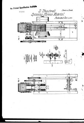
Figure 1 represents in elevation, a side view of the drawing frame. Fig 2 represents a plan of that part of the same frame which is situated above the dotted line passing as in fig 1. Fig 3 is a section of the same frame, the part above the dotted line in fig 1 being removed. This figure is a plan. Fig 4 is an elevation of the drawing frame as seen on the end when the filament is delivered from it. Fig 5 is an elevation as seen on the end where the hemp or roving enters the machine. Figures 6, 7, 8, 9, 10, 11, 12 and 13 are parts as seen detached from the machine. The same letters and signs are used to mark the same part as seen in any of the figures.
I shall now proceed to describe the drawing frame. A A A A represent the wooden frame work of the drawing frame. Across the top of this frame pass two shafts supported in proper boxes to which B B, two pulleys are fixed and about which is hatched belt C C C passes and by which it is carried. This belt is formed as follows: A number of the machine as shown in the drawings has 146 rows of iron or steel points are made and rivetted, or screwed firmly into iron plates called the hatched plates see fig 6; each row contains 7 points. There is moreover at each end of every row of points, a pin having a head at its top. These pins are somewhat longer than the points before fixing the pins to the hatched plate, a second plate of iron see fig 6 and fig 7.
Page 5.
pierced with nine holes at distances corresponding with the points and pins, is placed upon the points; the pins are then put in their places and riveted or otherwise fixed to the hatchet plate. This plate, x, is called the cleaver and can be moved freely up and down upon the points and pins; the pin heads preventing it from falling off or being removed; it is longer than the hatchet plate over which its ends project, one corner of the projecting part being cut off as seen in fig. 8. A strap of leather or of strong webbing 3 1/4 inches wide & long enough to form a belt about the pulley B.B' is pierced with holes in rows or otherwise, each row having five holes at distances equal to those of the five middle pins fig. 6. The distances of the end rows from each other are 7/8 inch and the holes do not form parallel rows lengthwise, but they are arranged as seen at the white spots C.C.C fig. 2. The strap thus pierced is passed between the cleaver and the points; the cleaver being riveted as seen fig. 6, and the points are inserted in a row of holes; this operation is repeated until all the holes are filled and the strap is then passed down upon the hatchet plate. In filling the strap, the rows of points are turned so that the wide spaces between the first and second points fig. 6 shall be to the right and left alternately in the successive rows, the cleaver having been put on to the points so that the middle from the corners shall all be towards the same end of the strap. Another strap of like dimensions with that just described but not pierced is then taken and laid upon a table and the strap containing the rows of points is placed directly over it, the points being upwards. Two rivets are then fixed between every two rows of points through both straps or instead of the rivets the straps may be strongly sewed together through the spaces between the rows of points. The straps with the points thus fixed to them are then passed round the pulley B.B' and the ends being fastened together they form the hatchet belt as seen at C.C.C. If the hatchet belt is liable to stretch by use, the under pulley D is required to keep it to a proper tension. The shaft of the pulley D has its guides run in bearings which may be moved up and down to adjust it as will be seen & understood from figs. 1 and 2. To keep the hatchet belt evenly upon the pulleys B.B' the guide fig. 7 is fixed to the frame A.A. the parts F.F.F. the guide point downwards and the hatchet plates pass between them. Fig. 1 shows the end of the guide in its place. Two cast iron rails F.F.F. figs. 1 and 2 are fixed parallel to each other upon the top of the wooden frame A.A. standing above it upon feet or pillars which are fixed to the frame. The distance between these rails is just equal to the length of the hatchet plates and their position such that the hatchet belt is between them. The end of both rails is one quarter of an inch above the line of the top of the
Page 6.
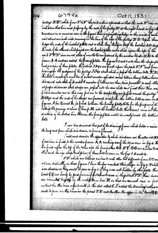
pulley B.B' while from F' to F" the rails incline upwards so that the end F" lies one inch above that line and passing by the end of the pulley B' at the right hand in fig 1 turns down in a curve as seen in the figure. There is a projecting ledge on the inside of each rail about one inch wide running in the line of the tops of the pulley B.B'. Upon these ledges the ends of the hatchel plates rest or slide. They therefore keep the hatchel belt straight. The ends of the cleaves which project over the hatchel plates, rest or slide upon the tops of the rails F.F.F'. Two curved plates of iron G.G are fastened by the wooden blocks H.H to the frame A.A and are called the forcing plates. The figures 1, 2 and 3 will show the shape, position and position of these plates. The pillars I.I are fixed upon the rails F.F and form bearings for the guidons of the pulleys J.J which is passed the bobbin belt K.K. This belt is made of a number of small wooden cylinders, called bobbins. Every bobbin has a slit sawed into each of its ends. A number of bobbins are then laid parallel to each other at proper distances and straps are passed into the saw-slits and fixed there. When any sufficient number are in this way put on to the straps they are passed round the pulleys J.J and the ends of the straps are fastened and form the bobbin belt, as seen in the figures. A tin tunnel L is fixed between the forcing plate G.G for the purpose of directing the passing or eliver of hemp M into the hatchel belt. This tunnel runs in the direction of the dotted line between the forcing plate until it nearly meets the bobbin belt.
I have thus described that part of the drawing frame which holds or eases the hemp and from which it is drawn to form a filament.
I will next describe the apparatus by which it is drawn out. The roller N.N of cast iron is fixed to the wooden frame A.A running along the top as seen in fig 4. There are fixed upon the top of the roller N.N the four rollers O.O.P.P.O.O are similar to each other and the size, shape and place of them will be seen in the figs 1, 2 and 4. P.P which are likewise similar to each other but different from O.O are not seen distinctly in those figures. I have therefore marked their shape in fig 9. P.P which is an elevation as they would be seen on fig 1 if they were not hidden by other parts. The levers Q.Q are hinged by pins forming fulcrums braces in the pillars P.P. These levers are connected together by the iron bar R so that one cannot rise or fall without the other rises or falls with it. The steel rollers S.S called the drawing rollers are made to run one the lower in the pillars P.P and the other, the upper, in the levers Q.Q.
Page 7.
fig 9 shows the holes which form boxes for the guides of the rollers. The drawing rollers are coupled by the plates T T to the shafts U U running in the pillars O O and connected by the gear wheels V V. The roller wheel has a projection on one side facing towards the hatched belt. A piece of cast iron W is fixed upon this projection and upon W is fixed the gatherer X.
This is made of plates of iron in nearly the form of an unequal four sided pyramid with its open base towards the hatched points and its truncated apex stemming between the drawing rollers being shaped as to conform to those portion of the rollers which are situated against it.
To prevent the end of the gatherer last described from being worn, two pieces of steel plate are secured upon the inside of both sides being shaped to conform to the rollers as the sides of the gatherer are. The top of the gather papes off towards the bottom belt and a piece of thin or thin iron plate is beat over it, on each side and papes down nearly to touch the hatched plates inside of the hatched points & outside of the hatched points. This is called the tail of the gatherer and is seen at X. The top of the gatherer has central slit cut through it so that the teeth of the comb 86 hereafter described can pass through it. There is moreover in the gatherer a false bottom hung by a joint at the end nearest the drawing rollers and capable of being swung upwards like a trap door; this false bottom has slits across it corresponding with those through the top. a is a fast pulley upon the shaft b to which the power is applied by means of a belt to drive the machine. a' is a loose pulley on the same shaft b on which the driving belt may run when the machine is at rest. On the end of the shaft b is the pinion c which drives the wheel d d fixed on the shaft U which is coupled to the lower drawing roller E.
Let us now suppose a row of hemp to be passed into the tunnel I o and the pulley B to be turned in the direction of the arrow, the bobbins lying between the rows of hatched teeth must be carried along with the hatched belt and as some of the bobbins by their connection in forming the bobbin folds, constantly pass out of the hatched belt at the right & others constantly pass into it on the left. When therefore the row of hemp passed into the tunnel I o meets the hatched points it is passed into them by the bobbins and passes along in the hatched belt until it arrives near the end F' of the rails F' F'. Now as the rails pass beyond the pulley B' to the right, and as the cleavers as fig 6. as has been before described pape on the top of the rails, it is evident that they will be passed upwards upon the hatched points and as the rowing of the hemp is always above them, this also must be lifted out of those points. Suppose that the end of the rowing is then passed through the gatherer X and then it be made to enter the drawing rollers. If the drawing rollers are now turned
Page 8.
faster than the hatches felt carrying the string, the string must be drawn out through the hatches point by the rollers forming a filament as much smaller than the original string, as the rollers move faster than the hatches felt. If however the relative motion be constant then the proportions will be true only when the mean size of the filament is compared with the mean size of the string, for the string is not supposed to be of equal size throughout and moreover the ends of the fibres of hemp cannot be distributed at equal distances in it, hence more of these ends will be taken into the rollers together at some times than at others. Now when many ends meet the rollers together, many fibres must be drawn out of the hatches together, and the filament be made larger than at other places, where the ends of fibres by being distributed in the rope at greater distances meet the rollers less frequently. To prevent as much as possible this inequality in the filament, I see the apparatus now to be described, which I call the regulator and the comb. A small cast iron frame e, e, e, e is fixed upon the wooden frame A A as seen in the drawing. The shaft f, f, is made to run on proper centres fixed in the frame e, e, e, and there are placed upon it the wheels g, g', (the shaft f, f with its connections is drawn separated from the frame at fig 10). These wheels are bored with a round hole and are capable turning freely upon the shaft f, f except as hereinafter described but are prevented by proper collars from slipping in the direction of the length of the shaft. A second shaft h, h, is made to run upon centres in the frame e, e, e parallel to f, f. These are firmly fixed upon the shaft h, h the wheels i, i', The wheel g and i have 50 teeth each and the wheels g' and i have 70 teeth each and the diameters of all the wheels are in proportion to the number of their teeth. The teeth of g play into those of i, and the teeth of g' play into those of i'. There are two locking pins a, b, c, d, e, f, g, h, i, j, k, l, m, n, o, p, q, r, s, t, u, v, w, x, y, z fixed upon the wheels g, g' - l, l' are two clutch boxes placed upon the shaft f, f. The clutch boxes are free to slide in the direction of the axis of the shaft, but pins are fixed in the shaft which project into a groove cut lengthwise on the inside of each clutch box, so that the boxes cannot turn round when the shaft. Several parallel grooves are turned into the body of each clutch box. The bodies of locking pins m, n, o, p, q, r, s, t, u, v, w, x, y, z are fixed upon the clutch box l, l' and the clutch box l, l' is connected with the clutch box l by a movable joint which permits its outer end to fall back towards the middle of the clutch box, it is prevented however from falling back except on the application of a slight force by a steel spring which is fixed at one end to the clutch box while the other end presses upon the hatches m. There is a stop so as to the clutch box to prevent the spring from forcing the catch m, outward beyond a certain distance. A slide bar o, o, is placed in the frame e, e, e, parallel with the shafts f, f, and h, h, and is capable of being moved in the direction of its length, and in that direction only.
Page 9.
arms p.p. are secured upon the top of this slide bar and pass from it towards the shaft f.f. and terminate directly over the clutch boxes l.l.' that is one arm over each clutch box. These are fixed to the under side of each arm p.p. a metal block or box g.g. which pass down to the clutch boxes. The under side of g.g. are formed in the shape of a portion of a hollow cylinder, and are grooved so as to embrace the clutch boxes upon the grooves before described upon them through about one third of their circumference. (Fig. 11. shows the slide bar o.o. and arms with the boxes g.g. separated from the other work. The figure represents the under side of these parts.) A long shaft or axle r.r. passes horizontally from under the slide bar o.o. to the right hand as seen in the drawings, until it projects beyond the frame A.A. (In fig. 2 this shaft is supposed to be broken off under the drawing rolled S.S. and the left hand part is removed.) r.r. is hung in centres which are fixed in the iron bearing s.s. This bearing is bolted to the frame A.A. and prevented from springing by the iron brace b.d. The arm t passes horizontally from the right end of r.r. and the arm t' rises vertically from its other end directly under the slide bar o.o. A steel spring u. is fixed upon the shaft r.r. near its middle. This spring runs along on the side of the shaft and turns upwards against the side of the arm t' until it reaches the top of t' against which it presses with its whole elastic force. A connecting rod passes from a hook in the top of the spring u. to another hook fixed in the underside of the slide bar o.o. - r is a bent lever (to fulcrum) being a pin which passes through its middle and unites it to the bearing w. which is fixed to the frame A.A. The vertical arm of the lever r is united at its top by a connecting rod with a hook which is fixed in the bottom of the slide bar and the horizontal arm of the same lever is united with the weight y. These hooks and connecting rods will be found in their places in fig. 5 from the description, no letters of reference being thought necessary. (It will be seen in fig. 1 that the shaft p.p. and the bearing s.s. are both situated behind a part of the frame A.A. - the spring u. the weight y and some other parts will likewise be found, in dotted lines, in the same figure.) From the arm t of the shaft r.r. there passes upwards the rod. t.a. t.a. (which is united with t by a movable joint) to the cross bar a.a. In rod t.a. passes through the middle of t.a. and receives a thumb nut upon its top. The connecting rods a.a. a.a. pass from the ends of the cross bar a.a. and are united by pins to the levers Q.Q. one rod uniting to each lever.
In addition to the parts heretofore described as connected with the shaft f.f. there is placed upon that shaft, the star wheel b.b. a side view or elevation of which is given detached at fig. 12. b.b. b.b. are plates of steel secured upon the sides of the projecting points of the star wheel.
Page 10.
and the breadth of these plates is greater than the thickness of the points of the wheel, so that they project over the sides of the points. The star wheel is fitted to the shaft f.f. like the wheels g.g. the shaft passing through a round hole in its centre, and proper collars are fixed to the shaft, on each side of it to prevent it from sliding in the direction of the length of the shaft. A wooden lever ba ba passes from a point near the star wheel horizontally to a point directly under the gatherer. A piece of brass is screwed upon the underside of this lever, near its middle, and a pin passes through this brass and through the cast iron pillars ja, ja which are fixed to the frame AA. This pin forms the fulcrum on which the lever turns. Two other pillars Pa, Pa rise from the frame AA on the sides of the lever ba to prevent it from having any lateral motion. A small piece of steel ga which I call the bob is united to the end of the lever ba by a pin passing through the middle, and likewise through two knuckles standing out from a piece of brass lb fixed to the underside of the lever ba. The lower end of the bob ga when the lever ba is in the position shown in the drawing is in the horizontal plane of the centre of the shaft f.f. but so far from that shaft to the right, as seen in figs 1 and 3 that the projections of the star wheel aa are just capable of reaching it and and throwing it upwards whenever the star wheel is turned round for the purpose.
A stop 2b of iron is screwed upon the top of the lever ba and a slight spring 3b tends to keep the top of the bob against the stop 2b. A pawl or click 4b having its lower end connected by a pin with the frame e.e. passes upwards through a hole or slot in the slide bar o.o by the side of the lever ba. The click 4b can move on the pin which unites it with the frame e.e. with which it forms a hinge joint so that its top may describe an arc in the extension of the length of the slide bar. A spring is fixed to the frame e.e. (seen in dotted lines in fig 3) which acts against the click 4b and tends to press it against the lever ba, so that whenever the end of that lever (at the left hand in figs 1 and 3) is raised above the top of the click, then the click slips under a piece of steel which is fixed upon the corner of the lever, where the click meets it and holds it up. But as will be hereafter seen it is required that the click should not remain under the lever except when the slide bar l' is carried by the slide bar o.o. as near the star wheel that the catchman is engaged against one of the plates 1ea therefore the pawl the click 4b from the lever ba except in the case before stated a piece of iron constituting a stop is screwed over one side of the hole or slot in the slide bar, so that whenever the slide bar is moved so far to the right as seen in fig 5
Page 11.
as to disengage the catch on from the star wheel, that the stop above described shall preclude the side of the disk 16 opposite to that against which the spring rests, and tending the spring disengage the disk from under the lever 5b. 5b is a weight upon the left arm of the lever 6a tending to depress the arm which it is attached. To the top of the lever 6a near its right end, as seen in figs 1 and 3 is united by a hinge joint the arm 6b, b, to each end of which are fixed rods 9b, 9b, which pass directly upwards through guide holes in the piece of cast iron W, each side of the gatherer, and on the outside of the same and are fixed by their tops to the arm 8b. The arm is formed of several parts of iron or steel teeth rivetted to an iron plate. The dots on the top of the plate in fig 2 show the number and place of the teeth. The several rows of teeth are directly over the slits in the top of the gatherer, which have been before described and on the application of a proper force to depress the arm, the teeth pass through these slits into the orrings of hump which is in the gatherer. Two cast iron pillars 9b are fixed to the frame A A A C and rise upwards above the lever 6a on each side of the same. A small lever 1e is placed between the pillars 9b directly over the lever 6a and is hung upon a pin which passes through 9b, 9b near their tops and through 1e. This pin forms a fulcrum or axis on which it turns to the right end of 1e as seen in figs 1 and 3 there is connected by a movable joint, the rod 2e which passes directly upwards through guide holes in the piece of cast iron W and the bottom of the gatherer before described. The left end of the lever 1e as seen in figs 1 and 3 is connected with the lever 6a by hooks. It will be readily perceived by this description and the figures, that when the right end of the lever 6a is depressed the right end of 1e will be elevated and carry the rod 2e upwards, which will lift the false bottom before described of the gatherer the teeth of the arm 8b passing at the same time through the slits before described made in the false bottom of the gatherer. Upon the shaft b, b is fixed the pulley 3e from which a belt passes to and over the pulley 3e fixed upon the shaft f, f. Upon the shaft h, h is fixed the pulley 5e and from that pulley 5e a belt passes to and over the pulley 6e which is fixed upon the shaft 7e running in proper braces in the upper part of the frame A A A C. The shaft 7e has the pinion 6e fixed upon it and this pinion drives a wheel 9e which is fixed upon the shaft 1d running in braces upon the top of the frame A A parallel to 7e and carrying besides the wheel 9e the pinion 2d. The pinion 2d drives the wheel 3d which is fixed upon the shaft of the pulley B.
To understand the operation of the regulator the arm
Page 12.
and other apparatus connected with and necessary to it, let us suppose the moving of hemp to be passed through the funnel I, and along the hatched belt and its end to be between the drawing SS, as has been before described. Let us also suppose that a constant rotary motion is given to the SS in the direction required for drawing out the filament through their connexion by the shafts f f, pinion V, which has been before described with the pulley a, which is driven by a belt carrying sufficient power. The motion from the pulley a, which likewise be communicated to the so and from thence through the belt passing from S to S, by which the shafts S S must also be driven, as moreover that the thumb nut upon the top of the rod I a has been so fixed that the filament between the rollers SS is of the required size, the catches m, m', m, shall all be engaged.
In this state of things the motion of the shaft S S will not be communicated to the wheels g, g', nor to the star wheel I a, but they will all remain at rest, with the shaft S S moving in them. As the hatched belt is under the condition stationary, the moving is not added to the drawing rollers, and it must therefore soon happen that the filament will become too as even as this is the case in a small degree, the upper drawing roller, which previously on an supported by the filament beneath it, must fall, and the ends of the levers Q Q, which project the rollers to the right in fig 1 and 2 must be depressed and the rods O a, the end bar 2, the rod I a likewise must drop downwards. Now the weight y, acting through the lever on the slide bar O O, tends constantly to draw the slide bar to the right as seen in fig 3. This tendency is ordinarily resisted by the connexion of the slide bar with the spring a, upon the shaft A A, the long metal arm b of which shaft is united by a joint with the When however the rod I a passes downwards, the arm b no longer supported, cannot take shaft A A, and the spring a, in their former position, but it suffers the weight to carry the bar to the right, the slide bar carrying with it the top of the spring a, which at the same time the shaft A A, depressing the arm b.
When the slide bar O O, moves as herein described to the right, the boxes g, g, and likewise the clutch boxes L' with it. The clutch boxes are by reason connexion with the shaft f f, as before described always enmeshed to revolve with the f f, and the catches m, and m are of course carried round with them. If therefore the clutches are carried far enough to the right as seen in fig 5, the catches m and m would strike the p and K respectively, but as the pin K is larger than k and approaches more nearly to the described by m, then the pin K approaches the described by m, the motion of the slide engages.
Page 13.
6794x Oct 11, 1831 301
against k, before m, can strike k'. It will beat me forward that as soon as m is engaged against k the wheel g will be made to revolve, this will drive the wheel i', by which the pulley 5 c must revolve, and the motion of 5 c will be communicated by its belt to the pulley 5 e and from thence through the pinion 5 e the wheel g e, the pinion 3 d, and the wheel 3 d to the pulley B by the revolution of which the hatched belt will be moved and the roving advanced towards the drawing rollers S S, with a certain velocity which will be found by measuring the several pulleys, wheels and pinions which are concerned in communicating and multiplying the motion. If by the advance of the roving with the velocity thus obtained, as many fibres of hemp are presented to the drawing rollers as are required to increase the filament to its proper size, then the upper drawing roller is raised by the filament thus increased and the slide bar o o, by means of its connexion with the upper roller (through the connecting rod and links, the spring m, the shaft s s, the arm t, the rod 1 a, the crank bar 2 a, the rods 3 a and the lever Q Q) will be carried to the left as seen in fig 5 and the clutch boxes will be moved with it, by which the catch m, will be disengaged from the pin k, when the wheel g and the several pulley and wheel and pinions by which it gave motion to the pulley B must come to a state of rest and the further advance of the roving to the drawing rollers will cease.
Let us suppose however that when m and k are engaged and the roving advancing as heretofore described, the size of the filament does not increase, but that from the smallness of the roving, the fibres are presented to the drawing rollers so unfrequently that the filament diminishes yet more in size. In this case the upper roller will continue to fall and the slide o o, connected with it by the apparatus before described, will continue to move to the right as seen in fig 5, until the catch m engages the pin k' upon the wheel g' and carries it round with it, then it will be seen that the wheel g' is larger than the wheel g, while the wheel i' is smaller than the wheel i, in this new connexion therefore the shaft h and the pulley 5 c will be driven faster than they were when their motion was derived from the wheel g, and the greatest velocity of the pulley 5 e being communicated by the belt pulley, wheels and pinions as has been before described to the hatched belt the roving of hemp must be advanced more rapidly to the drawing rollers S S and by this the filament receives a greater accession of fibres in a given time. When by this accession of fibres the filament is increased to the proper size, the upper roller will rise and the clutch boxes will be carried to the left, the catch m being disengaged from the pin k' and the hatched belt and roving will part.
It will be seen that while the wheel i' is driven by the wheel g' the wheel g must be driven by the wheel i, in this state of things the pin k will make more
Page 14.
resolutions in a given time than the catch m, and as they come in contact with each other it is not necessary that k should pass m without a permanent locking. Now when k strikes m in this way the catch m is raised the sides opposite to those which were struck when k was driven by m, and to let the spring k pass each other the sides or corners of both m and k which would otherwise catch and interrupt the motion are taken off and the end of the pin and the edge of the catch form inclined planes which sliding upon each other the catch is forced backwards against the resistance of the spring hitherto described, and thus k passes by m; the spring always causing m to return to its former position after k has passed it. Figure 14 shows the form of m and k. l.d. l.d. are the faces which strike when k is driven by m, and s.d. s.d. are the inclined planes which meet when the wheel is driven by the roller n.
Let us now consider the operation when the filament is too large, supposing that the advancement of the moving, as before described, brings so great a number of the ends of fibres in contact with the drawing rollers that the filament not only attains a sufficient size but becomes too large. In this case the upper roller supported upon the filament is elevated above its ordinary place, and by means of the connections hitherto described the arm t is carried upwards, the shaft d, rolling back the top of the spring u is carried to the left and the slide o o and the elastic braces also from their common position before described must be carried to the left. This brings the face of the catch m' into contact with the projection of one of the plates 5 a, and from this engagement the star wheel is a is made to revolve with the shaft f. As soon as this revolution commences, one of the plates 5 a upon one of the points of the star wheel must strike the bob 9 a, and throw the end of the lever 6 a, to which it is attached, upwards which will be caught and held by the fall or click 4 b. The length of the fall or click 4 b is such that it catches the lever 6 a when it is carried to the highest point that it can be carried by the star wheel consequently when it is not caught by the point of the star wheel does not by their continued revolution strike with much force if they strike at all upon the bob. It will at once perceive by an inspection of the drawings that when the left end of the lever 6 a to which the bob is attached is thrown upwards the right end must be depressed, and the arm 8 b be carried downwards at the same time the right end of the lever 6 a must from the connection of that lever as before indicated with the bob 6 a be carried upwards and its motion being communicated by the rod 2 c to the false bottom of the gatherer that will become exposed. The condition of the arm and of the false bottom of the gatherer will cause the teeth of the comb to be passed into the column of
Page 15.
6794x Oct 11, 1831 303
roving which is in the gatherer. This will prevent the fraying of the fibres of which the roving is made up to the drawing rollers while some of the fibres, the ends of which are already in the drawing rollers, will be broken off and thus the size of the filament will be speedily reduced to its proper dimensions. It may happen on the passage of a lock of tow or a knot of entangled fibres through the rollers, that they will be separated to a considerable distance. In this case when the clutch boxes on the shafts f f are brought against the collars of the wheels g and 4a, so that the slide o o cannot pass any further to the left, the spring u, yields as the arm b rises on the separation of the rollers and as soon as the tow or other matter has passed and the upper roller falls, the spring u, returns by its elasticity to its former state. When the filament has been reduced to the proper size the upper roller must consequently fall to the place which that size of filament determines. This motion being communicated to and modified by the various parts connecting the upper roller with the slide o o, as heretofore described, the slide bar must move to the right as seen in fig 5 and the pall or click u b being by the action of the stop fixed as heretofore described upon the top of the slide bar carried from under the corner of the lever b a the weight 5 b will cause the arm of the lever to which it is attached to fall, by which the arm will be raised and the false bottom of the gatherer will be depressed and thus no further interruption be offered to the passage of the roving to the drawing rollers.
The only parts of the drawing frame remaining to be described are the cone pulley 7d, upon the shaft b, the shaft 8d and the pulleys 9d and 10e upon the same; and the stopping guide 2e 2e 2e. But as these parts are connected in their use with the bobbin frame, I shall notice them as may be necessary hereafter.
Having thus described the construction and mode of operation of the principal parts of the drawing frame I shall proceed to describe the second part of the machinery, viz. the bobbin frame by which the filaments is twisted and wound up.
Figure 14 represents an elevation of this frame in its position as connected with the drawing frame. Fig 15 is a plan of the bobbin frame and Fig 16, an elevation as seen in the end next the drawing frame. Figs 12 and 13 may appear as continuations of Figs 1 and 2. I have however marked them as distinct figures in accordance with the division adopted for describing the whole machine. The wooden frame of the bobbin frame is presented at 6e, 6e, 6e, 6e, etc. of this, near its bottom passes the shaft 7e having its ends placed in proper boxes upon the frame 6e 6e 6e. Upon the shaft 7e is
Page 16.
304 6794x Oct 11, 1831
fixed the one pulley 5c, which is driven by a crossed belt running from the cone pulley 7d upon the drawing frame. There is moreover upon the shaft 7e the two gear wheels 9. The flyer is shown at 1f, 1f to its guides, both of which are hollow, running in proper boxes in the frame 6e 7e - 2f 3f, are sheaves or pulleys over which the yarn seems to be wound upon the bobbin. The bobbin spindle 3f runs in a box upon the frame 6e, 6e and in a bar marked 4f which is placed upon the back of the flyer and varies from one side to the other of the same and is capable of sliding upon the boxes in the direction of their length. It will be understood that the spindle passes through the hollow axles of the light guides of the flyer. As in fig 14, the hole through the guide gear being somewhat larger than the spindle. 5f is the bobbin placed upon the spindle and kept in place by a pin which passes through an ear or small piece of iron which is fixed to the bobbin and likewise through the spindle.
The pulley 6f is fixed to the bobbin spindle and the pulley 7f is fixed to the flyer. The drum 9f has its guides placed in proper boxes fixed to the frame 6e 6e. The bevel wheel 1g is fixed upon the shaft of this drum and being driven by the bevel wheel 9e causes the drum to revolve. A belt passes from the drum 9f to the pulley 6f and another belt from the same drum to the pulley 7f. The binder pulley 2f rests upon the belt which passes from the drum to the pulley 6f, for the purpose of keeping that belt at a proper degree of tension, which may be regulated by weights placed upon the frame in which the pulley revolves. Such frame as will be seen in the figures, is hung by guides which move in the frame 6e 6e 7e.
From what has now been specified it will be seen that motion being given as heretofore described, to the drawing frame, such motion must be communicated from the pulley 7d on that frame, by the belt to the pulley 8e on the bobbin frame and from thence, by the bevel wheels 9e and 1g, to the drum 9f. It must moreover, be evident that the pulleys 6f, and 7f will at the same time be made to revolve as they are connected by belts with the drum 9f. The filament therefore as delivered from the drawing rollers, being passed through the hollow guides on the left end of the flyer fig 14 and over the pulleys 2f, 2f, to the bobbin to which its end is fastened, must be, by the revolution of the flyer and bobbin, re-wound. In order however that it may be wound upon the bobbin it is necessary that the bobbin and flyer should not make an equal number of revolutions in an equal time.
Page 17.
6794x Oct 11, 1831 305
Now it will be seen that the end of the drum g f from which the belt passes to the pulley 7 f is larger than the other part of the same drum while the pulleys 6 f and 7 f are nearly equal in size.
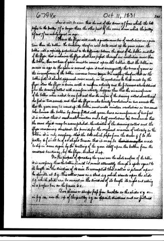
Hence the flyer will make a greater number of revolutions in a given time than the bobbin. The tendency therefore will be to wind up the yarn upon the bobbin with a rapidity proportional to the difference between the speed of the bobbin and that of the flyer, that is whenever the flyer shall have passed through one revolution more than the bobbin, then one turn of yarn must be wound upon the bobbin. But the bobbin increases in size as the yarn is wound upon it and consequently the turns of yarn as the circumference of the bobbin increases become longer. It is necessary therefore that as the bobbin fills, it should approach more nearly in its revolutions to those made by the flyer. Now the flyer is driven with a uniform velocity and the filament also is drawn from the drawing rollers with a uniform velocity. Suppose then that the circumference of the bobbin when naked be one foot and that the surface of the drawing rollers move through one foot in two seconds, and that the flyer makes twenty revolutions in two seconds then that the yarn may be wound up, the bobbin must make nineteen revolutions in two seconds. When however the bobbin by being filled with yarn, has a circumference of two feet it is evident that it must make nineteen and a half revolutions in two seconds that the same object may be accomplished, the velocities of the drawing rollers and the flyer remaining constant. To provide for the required increase of velocity in the bobbin it is only necessary that the belt which passes from the drum g f to the pulley 6 f shall be of a slight tension that it may be that it may be made to slip in some degree by the pulling of the yarn itself upon the bobbin from the constant tendency, by the flyer, to wind it up.
For the purpose of spreading the yarn over the whole surface of the bobbin it is necessary that the bobbin should be moved alternately through a space equal to its length in the direction of its axis. To accomplish this, a collar is placed upon the spindle at 3 g. This collar runs in a stud 4 g which stands upon the slide 5 g which slide can be moved in the direction of its length its right end resting in a proper box on the frame b e.
Two chains or straps pass from brackets on the slides 5 g seen in fig 14, over the top of the pulley 6 g in opposite directions and are fastened
Page 18.
to the periphery of the pulley on different sides of the same. Two other chains or straps similar to those above described pass from brackets on the slide or rod 7g and are connected with the small pulley 8g. The pulley 6g and 8g are upon the same shaft 9g the quidgens of which run in proper boxes in the frame 6b. It will be understood that the arrangement of chains or straps connecting the slide 5g with the pulley 6g and the slide or rod 7g with the pulley 8g is similar to that often used for moving the pistons of pumps or fire engines. Upon the shaft 1h which runs in proper boxes in the frame 6b is fixed the heart wheel 2h. Two pins 3h 5h are fixed to the slide or rod 7g and their sides are in contact with the heart wheel on opposite sides of the same. Upon the shaft 1h is fixed the pulley 4h from which a belt passes to the pulley 5h upon the shaft 6h. Upon the same shaft 6h is fixed the pulley 7h from which a belt passes to the pulley 8h upon the shaft 9h, upon which shaft 9h is fixed the pulley 1k. The shafts 6h and 9h run in boxes fixed to the frame 6c 6c. The pulley 1k is connected by a belt with the pulley 12 hereof or referred to upon the drawing frame. It will be seen that there is upon the same shaft with 1k the pulley 9d. Upon this pulley 9d a belt passes to and rounds the shaft 1b.
To understand the effect of the parts last described in giving an endless motion to the bottom, suppose the shaft 1b of the drawing frame to revolve, its motion will be communicated by the belt to the pulley 9d which will turn the pulley 1k upon the same shaft with it; the rotation of 1k will give motion to 1k whence as will be at once perceived the pulleys 8h, 7h, 5h and 4h together with the heart wheel 2h by reason of their connection as herebefore described must all revolve.
The revolution of the heart wheel gives a rectilinear alternating motion to the rod or slide 7g. This rod or slide from its connection with the pulley 8g communicates a circular alternating motion to that pulley, which motion must likewise be communicated to the pulley 6g, and 6g must communicate by reason of the connection as herebefore described a rectilinear alternating motion to the slide 5g. It is evident that the motion of 5g will be communicated to the spindle 3f, the bottom 5f, the pulley 6f and the bar 4f, which forms of the boxes in which the spindle revolves. The belt which passes from the pulley 6f to the drum 9f will during this endless or rectilinear alternating motion of the bottom pass along over the top of the drum 9f and the hinder pulley 2g.
There remains to be described only the apparatus by which the motion
Page 19.
6794x Oct 11, 1831 307
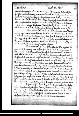
the machine is destroyed, whenever the thread or yarn is from any cause broken. The first part of this is called the stopping guide and is seen on the drawing frame marked 2 c. 2 c. fig 1 and 2. It is a rod of iron, hung by a hinge joint at one end, to the frame A A A a. From the end which forms the joint the rod passes horizontally towards the bobbin frame which is nearer to the frame, it is bent so as to pass directly under the filament or yarn, where it is under the operation of drawing, from this it is again bent upwards so as to form a sort of hook, which lies against the side of the yarn as seen in fig 1.
Upon one side of the rod thus described, is rivetted a piece of iron for receiving a main cord as seen in fig 2, and through this fork as here seen, the main belt by which the machine is driven passes from a drum above to the pulley a. So the end of the stopping guide next to the bobbin frame is fixed a cord which passes from it and over the sheave or pulley b c placed upon the bobbin frame, seen at fig 16, and to the end of this cord a small weight is attached.
To understand the operation of this apparatus, let us suppose the main belt to be running upon the fixed pulley a by which the machine must be kept in motion. Under this condition if the yarn be forming and whole, and attached to the bobbin it will be drawn in a right line from the drawing rollers to the axis of the flyer. At the same time the weight attached to the cord which passes from the stopping guide, as before described, tends constantly to draw the end of the stopping guide towards the pulley a c, but as the end of the stopping guide, passes upwards by the side of the yarn, it cannot move toward the pulley a c without carrying the yarn before it and in this it is resisted by the whole tension of the yarn. Under these conditions therefore, the main belt will continue to run on the pulley a. When however, the yarn breaks, the force which kept the stopping guide in its place is destroyed, and it is moved at once by the action of the weight upon the cord as before described, towards the pulley a c and by this action, the main belt is carried by the forked guide before described on to the loose pulley a' and consequently the motion of the machine will no longer be maintained.
The particular form of stopping guide here described is united to a keyway which is driven by a belt passing from a drum placed above it. Some modification of form will be required to suit it to a belt passing to it in another direction. But this and other modifications of form, such as adapting it to a clutch box instead of a belt, it is not necessary to describe, as they cannot change of character or principle in the apparatus.
Page 20.
308 6794x Oct 11, 1831
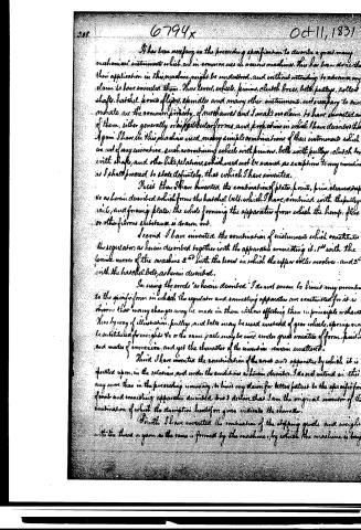
It has been necessary in the preceding specification to describe a great many mechanical instruments which are in common use in various machines. This has been done that their application in this machine might be understood, and without intending to advance any claim to have invented them. Thus levers, wheels, pinions, clutch boxes, belts, pulleys, rollers, shafts, hatched points, flyers, spindles and many other instruments, not necessary to our narrative, are the common property of mechanics and I make no claim to have invented any of them, either generally or in particular forms and proportions in which I have described them. Again I have in this machine used many simple combinations of these instruments which are not of my invention, such as combining wheels with pinions, belts with pulleys, clutch boxes with shafts, and other like relations, which need not be named as exceptions to my invention as I shall proceed to state definitely, that which I have invented.
First then I have invented the combination of plate, point, pin, cleaved rope, as herein described which forms the hatched belt, which I have combined with the pulley, rail, and forming plate; the whole forming the apparatus from which the hemp, flax or other fibrous substance is drawn out.
Second I have invented the combination of instruments which constitutes the regulator, as herein described together with the apparatus connecting it, 1st with the forming motor of the machine 2nd with the lever in which the upper roller revolves—and 3rd with the hatched belt, as herein described.
In using the words “as herein described” I do not mean to limit my invention to the specific form in which the regulator and connecting apparatus are constructed for it is obvious that many changes may be made in them without effecting them in principle or character. Thus by way of illustration, pulleys and belts may be used instead of gear wheels, springs may be substituted for weights &c or the same parts may be used under great varieties of form, position and modes of connection, and yet the character of the invention remain unaltered.
Third I have invented the combination of the same and apparatus by which it is operated upon, in the relations and under the conditions as herein described. I do not intend in this any more than in the preceding summary, to limit my claim for better patent to the specific form of said and connecting apparatus described but I declare that I am the original inventor of the combination of which the description heretofore given indicates the character.
Fourth I have invented the combination of the stopping guide and weight with the thread or yarn as the same is formed by the machine, by which the machine is being
Page 21.
6794x Oct 11, 1831 309
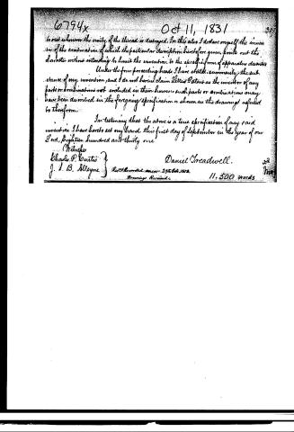
to rest whenever the unity of the thread is destroyed. In this also I declare myself the inventor of the combination of which the particular description heretofore given points out the character without intending to limit the invention to the specific form of apparatus denoted.
Under the four preceding heads I have stated summarily the substance of my invention, and I do not herein claim Letters Patent as the inventor of any parts or combinations not included in them; however, such parts or combinations may have been described in the foregoing specification or shown in the drawings referred to therein.
In testimony that the above is a true specification of my said invention, I have hereunto set my hand this first day of September in the year of our Lord, eighteen hundred and thirty one.
Witness:
Charles P. Curtis
J. I. B. Alleyne
Daniel Sreadwell.
Rec'd & Recorded 29th Oct. 1831.
Drawings Received. 11,500 words
Published accounts: journal notice
Notice in the monthly list of patents, with remarks
Journal of the Franklin Institute, new ser., vol. 9 (1832), p. 229 · View the page
14. For a Machine for Spinning Hemp and Flax, and other fibrous substances; Daniel Treadwell, Boston, Massachusetts, October 11.
Remarks. The description of this machine extends to upwards of forty pages, and refers to sixteen figures, in which its respective parts are repre: sented by drawings. From the nature of the case, it is not possible to present a good idea of the instrument without giving the whole of these. The subjoined extracts, however, are all that we can at present offer. The patentee observes, that "Before proceeding to the description, it will be useful to state, that spinning may be considered as consisting of two operations, first the drawing out of the filament to the required fineness, from a mass of the fibrous material, commonly in the state of roveing, or rolls; and second, the twisting of the filament so drawn, which completes the formation of the thread, or yarn. In some modes of spinning both of these operations are carried on at the same time in the same portion of the material; that is, the filament is elongated during the operation of twisting. In the invention herein described, the filament is drawn to the proper size before twisting it in any degree." The patentee in his summary at the end of his specification, observes, that it has been necessary for him to describe a great many well known mechanical instruments, in order to show their application in this machine, without intending to advance any claim to the invention of them; and then proceeds to state, under four distinct heads, what he considers as original. First. The combination of plates, points, pins, clearers, straps, &c. as described, which forms what is called the hatchel belt, and which, with its appendages, serves to draw out the material to be spun. Second. A combination of instruments which constitute what is called the regulator, with the manner in which it is connected to, and operates with, the other parts. Third. The combination of the comb, and apparatus by which it is operated upon, for the purposes described. Fourth. A stopping guide and weight, by which the machine is brought to rest, wherever the unity of the yarn is destroyed. These claims are guarded by stating that it is not intended to limit them to the precise forms represented, as these may, in every case, be varied, but to embrace that principle, or mode of operation, the character of which is pointed out in the particular description given. From a very careful examination of the whole subject, as well as from direct information, and from confidence in the solid talents of the patentee, we are of opinion that this machine will prove to be one of great value. 15. For an improvement in the Manufacturing water proof Wool and Fur Caps; Laban L. Macombier, Gardiner, Maine.
About this record
- Patentee
- DATAMP
- Date
- the Name and Date index of patents, DATAMP, USPTO records
- Invention
- DATAMP
- Listed in
- the Name and Date index of patents, DATAMP, USPTO records, Jim Shaw's X-patent list, the Journal of the Franklin Institute, Burke's List of Patents (1847)
- Burke's 1847 Patent Office list gives the same patent.