

Drawings and documents
National Archives restored drawings: drawing
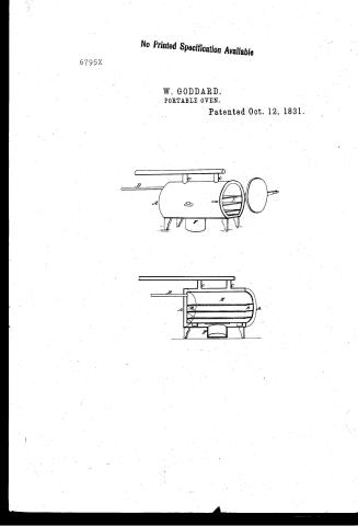
W. Goddard's Patent Drawing for a Portable Oven

National Archives, Restored Patent Drawings (Record Group 241) · Full-size scan at the National Archives · Catalog record
Show the text on the drawing Hide (75 words)
Words on the drawing as machine-read by the National Archives; not checked. Useful mainly for searching.
126. STOVES & FURNACE / 7831. / Donv, / [154] Domestic Ovens. / 147] / Section / W. GODDARD / Portable Oren / A. Dutside Cylinder / B. Inside Cylinder or tining / C. Flues / D. Tabe yor escape of steam / III. Oven / R. Furnace / s Mir / G Strickland Del / Patent Office 25 at 1838 / #6795* / CLASSIFICATION / DIV 6795x ISION. / Made under the direction of the Commisioner of / Patients in conformity with Out 3d. March 1837 / old
USPTO scan
The patent as scanned by the USPTO
-
 Page 1
-
 Page 2
-
 Page 3
-
 Page 4
-
 Page 5


U.S. Patent and Trademark Office · Google Patents
Show the transcription Hide (1,125 words)
Machine transcription (LightOnOCR) of the pages as scanned by the USPTO, most of them the handwritten copies made when the records were restored after the 1836 fire. Not checked; it can misread handwriting, so compare it with the scan.
Page 1.
No Printed Specification Available
6795X
W. GODDARD.
PORTABLE OVEN FOR ROASTING AND BAKING.
Patented Oct. 12, 1831.

a, Furnace.
b, Outer cylinder and lining may be filled with non-conducting substance.
c, Inner cylinder.
d, Supporters of iron.
e, Tube and stopper.
f, Flue.
Page 2.
No Printed Specification Available
6795X
W. GODDARD.
PORTABLE OVEN.
Patented Oct. 12, 1831.

Page 3.
Oct. 12, 1831 6795X 343
William Goddard, Portsmouth, New Hampshire
Letters Patent.
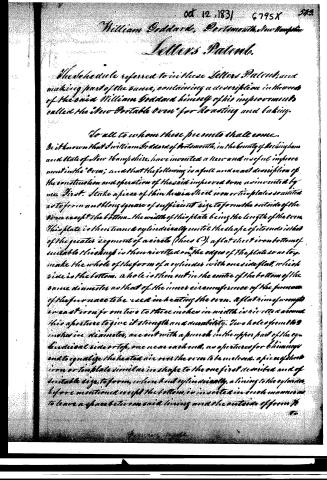
The schedule referred to in these Letters Patent, and making part of the same, containing a description in the words of the said William Goddard himself of his improvements called the "New Portable Oven" for Roasting and baking.
To all to whom these presents shall come.
Be it known that William Goddard of Portsmouth, in the county of Rockingham and State of New Hampshire, have invented a New and useful improvement in the "Oven"; and that the following is a full and exact description of the construction and operation of the said improved oven as invented by me. First. I take a piece of thin heavy sheet iron or tin plate so united as to form a long square of sufficient size to form the outside of the oven except the bottom—the width of this plate being the length of the oven. This plate is then turned cylindrically until the shape of its ends is that of the greater segment of a circle (thus C), a flat sheet iron bottom of suitable thickness is then rivetted on the edges of the plate so as to make the whole of the form of a cylinder with one side flat, which side is the bottom. A hole is then cut in the center of the bottom of the same diameter as that of the inner circumference of the furnace of the furnace to be used in heating the oven. A flat rim of wrought or cast iron from two to three inches in width is rivetted around this aperture to give it strength and durability. Two holes from two inches in diameter, are cut with a punch in the upper part of the cylindrical side or top, one near each end, as apertures for chimneys and to equalize the heated air over the oven to be melons. A piece of sheet iron or tin plate similar in shape to the one first described and of suitable size, to form, when bent cylindrically, a lining to the cylinder before mentioned except the bottom, is inserted in such manner as to leave a space between said lining and the outside of form to
Wm. Goddard
Page 4.
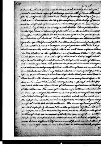
to 1 inch, which space may be closed at the ends by bending the front and back edges of the lining and rivetting them to the outer plate or by a rim of sheet iron or tin of corresponding size. Two holes are then made in the upper surface of the lining opposite and corresponding to the holes in the outer surface, the lower edges of the lining being also rivelled to the bottom. Through these holes in the top, flues or chimneys of sheet iron or tin are then inserted of sufficient length to create such a draught as is required for the combustion of the coal. These two chimneys are then connected by a horizontal funnel fitted with a damper and of a length to conduct the heated air or gas to any required outlet, a head of sheet iron or tin, either single (or lined, so as to leave a space between the two plates) is then fitted on and fastened to the end for the back of the oven. Near the top of this back a hole of sufficient size is cut with a punch to admit a tube for the escape of steam, whenever required. The aforesaid spaces between the linings and outside covering may be filled with atmospheric air, wood ashes, powdered charcoal, or any other suitable nonconducting substance. A piece of sheet iron of a similar shape to the two before mentioned is then bent into the same cylindrical form and of such sizes as to leave when inserted into the other cylinder a space from ¾ to ¾ of an inch between the outside of this inner cylinder and the lining of the outer one. The inner cylinder having a bottom and end similar and corresponding to the bottom and end of the outer cylinder, except that the bottom of the inner one is whole, a hole is then made near the top of the end of the said inner cylinder, corresponding in every respect to the hole in the outer one. The inner cylinder just described is properly thrown into the outer cylinder, together with its lining forms a nonconducting cover or case on the centre of the bottom of the oven is secured a plate of iron wrought or cast for the purpose of defending the bottom from the direct heat of the furnace below. Supports of iron are next fixed on the bottom of the inner cylinder or oven at suitable distances for the purpose.
Page 5.
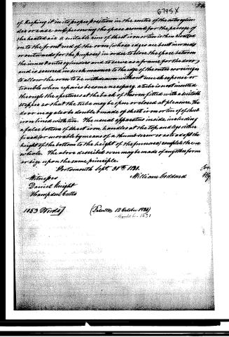
of keeping it in its proper position in the centre of the outer cylinder or case and preserving the space around for the passage of the heated air. A suitable rim of sheet iron or tin is then bent over onto the front end of the oven (whose edges are best in wood or outer wood for the purpose) in order to close the space between the inner and outer cylinders and to serve as a frame for the door, and is secured in such manner to the edge of the outer covering as to allow the oven to be withdrawn without much expense or trouble when repairs become necessary. A tube is next inserted through the apertures at the back of the oven fitted with a suitable stopper so that the tube may be open or closed at pleasure. The door may also be double & made of sheet iron or tin of sheet iron lined with tin. The usual apparatus inside, including a false bottom of sheet iron, handles at the top, and legs either fixed (or movable by means of a thumb screw so as to adapt the height of the bottom to the height of the furnace) complete the oven whole. The above described oven may be made of any other form or size upon the same principle.
Portsmouth Sept. 31st 1831.
Witnesses
Daniel Knight
Hampden Butts
William Goddard
1153 Words
(Patented 12 October 1831)
Angus 6. 1831
Published accounts: journal notice
Notice in the monthly list of patents, with remarks
Journal of the Franklin Institute, new ser., vol. 9 (1832), p. 231 · View the page
16. For a New Portable Oven for Roasting and Baking; William Goddard, Portsmouth, Rockingham county, New Hampshire, October 12.
Remarks. This oven is formed of three separate sheets of iron or tin, and is in the form of a segment of a cylinder: in making it, sheet metal of suitable dimensions is bent round so as to form. about three-fourths of a circle, the edges are then joined by a flat piece, which forms the bottom of the outer case. A second piece of sheet metal is then bent into the same form, but is to be the segment of a smaller circle than the first, so that when slipped into it, there will be the space of an inch between them; this when in its place, is to be rivetted to the bottom of the outer case. A plate is to be put on at the back end, and a rim fixed, enclosing the space between the two at the front. The space may be filled with charcoal, or other bad conductor, or may be occupied by air only. Through both these vessels two holes for flues are to be made at the top, one near to each end, and these are to lead to one common pipe, furnished with a damper; another hole is to be made for the escape of steam. Heat is to be applied by a round stove, or furnace, under the middle of the oven, a hole being perforated through the bottom sufficiently large in diameter to receive it; and a ring of cast, or of wrought, iron is rivetted to the bottom, in order to give the requisite strength to this opening. A third box, made in the form of the other two, constitutes the oven proper. This is made exactly in the form of those already described, and is to be slipped into its place within them, leaving a space between it and the second box, and also between its back end and the first, which space is for the passage of smoke and heated air from the fire, around the oven, to the flues. The bottom of this is exposed to the action of the fire in consequence of the perforation made through the outer box. When this last is secured in its place a door is to be fitted to it in the usual way. There is no claim made to any part of this apparatus; the security of the patent, therefore, must depend upon the general novelty of its construction.
About this record
- Patentee
- DATAMP
- Date
- the Name and Date index of patents, DATAMP, USPTO records
- Invention
- DATAMP
- Listed in
- the Name and Date index of patents, DATAMP, USPTO records, Jim Shaw's X-patent list, the Journal of the Franklin Institute, Burke's List of Patents (1847)
- Burke's 1847 Patent Office list gives the same patent.